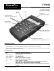
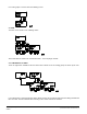
ZTH100 HomePro Programmable Radio Frequency Control Remote Transmitter Operating Instructions RF Home Automation ALL ON Button OK Button Menu Button (Activates menu display) Navigation Buttons (toggle left or right thru menus) Cancel Button (cancels actions) ALL OFF Button Scene button (Brings up scene menu) Numbered Speed Buttons (Grants quick access to groups and scenes) BEFORE YOU BEGIN... READ ALL INSTRUCTIONS Remove battery cover on rear of transmitter.
Table of Contents 1. INTRODUCTION PAGE 1.1 Getting Started................................................................................................................ 3 2. HOMEPRO PRODUCTS 2.1 Other HomePro Lighting and Appliance Products.................................................................. 3 3. GENERAL OPERATION 3.1 System Description. ................................................................................................................ 3.2 Remote Transmitter Software features. .
1. INTRODUCTION 1.1 GETTING STARTED Congratulations on your purchase of the ZTH100 and other HomePro components. This manual will guide you in understaning the full capabilities of the HomePro Sytem and operation of the Remote Transmitter. 2. HOMEPRO RF PRODUCTS 2.
1. HOW TO USE THE ZTH100 FEATURES 4.1 MENU NAVIGATION AND SELECTION Pushing the “Menu” button will activate the menu display.: a. and keys are used to navigate through the menu. All menu levels wrap around. b. activates the currently selected menu item. c. (or Clear) cancels the currently selected item and will in most instances step back to the previously selected menu level. If used from top menu level the Remote will return to clock display.
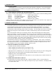
4.2.1 ADD MODULE TO GROUP Adding a module to a group using the menu is done this way: Alternatively if the group has been named, the name shows up instead of the number. To add more units repeat the procedure “ADD UNIT TO GROUP” 4.2.2 ADD MODULE TO SCENE. Adding a module to a scene is done this way: Note that hitting “C” will not clear units that already have been stored in the selected scene. A module is stored when “Switch included” is shown in the display.
4.2.3 EXCEEDING NODE LIMIT. This application supports up to 64 modules. If the user tries to add more than 64 modules to a group or scene this message will be displayed: However the module will be given a valid ID and it will be used as a repeater if it supports this functionality, but it cannot be directly controlled by this remote. 4.2.
4.2.6 REMOVE MODULES FROM GROUP/SCENE. Clear cancels the current selection. Navigation keys only work if more than one group or scene exists. 4.2.7 DELETE GROUP/SCENE Scroll left or right to find scene. HomePro by ADVANCED CONTROL TECHNOLOGIES, INC.
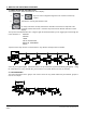
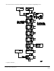
If no active groups or scenes exists the following occurs: 4.3 TIMER The timer menu consists of the following menus: Timer information is stored in the remote transmitter – not in the plug-in module. 4.3.1 CREATE/EDIT A TIMER There are eight timers available for the user. Each timer controls one of the existing groups as chosen by the user. If an existing timer is selected that timer will be edited. Pressing the clear button will cancel the editing and leave the timer as it was.
Once a timer has been selected the following flow is executed when creating/editing a timer: If a group is named the group name will be shown. HomePro by ADVANCED CONTROL TECHNOLOGIES, INC.
4.3.2 DELETE TIMER When a timer is no longer needed it can be deleted using “Delete a timer” menu. 4.4 CHILD PROTECTION Child protection is a feature that protects against unintended use of a module. For this feature to work the module must support it. ZTH100 Operating Instructions 060902 10 HomePro by ADVANCED CONTROL TECHNOLOGIES, INC.
If a module button is pressed you will get: or depending on which of the two options you selected. 4.5 BURGLAR DETERRENT When in burglar deterrent mode the remote will randomly turn module on and off in the time interval set by the user in the “customize time” menu. By default no modules are included in the burglar deterrent mode. So the first step the user should perform, is to include the units that should be used during burglar deterrent. See section 4.5.
4.5.1 ACTIVATE BURGLAR DETERRENT Activating burglar deterrent will will take the user through a time period customization and put the remote into a special mode where it will stay until burgular deterrent is cancelled. By default no units are included in burglar deterrent. This message will be shown when the user tries to activate burglar deterrent: ZTH100 Operating Instructions 060902 12 HomePro by ADVANCED CONTROL TECHNOLOGIES, INC.
4.5.2 EXCLUDE UNIT An included module can be excluded once again using this menu. Note that by default no modules are included in the burglar deterrent mode. 4.5.3 INCLUDE UNIT When first activating burglar deterrent the modules that the user wants to use should be included using this menu. In addition an excluded module can be included once again using this menu. HomePro by ADVANCED CONTROL TECHNOLOGIES, INC.
4.6 SETUP The setup menu is used to access system functions. The layout is as follows: 4.6.1 SET TIME 4.6.2 DISPLAY CONTRAST “C” cancels the contrast adjustment and returns to idle. Default contrast is 50% which is restored whenever the batteries have been removed. ZTH100 Operating Instructions 060902 14 HomePro by ADVANCED CONTROL TECHNOLOGIES, INC.
4.6.3 SETUP ALL ON/OFF Using this menu it is possible to customize the way All on/off works. Units can be included or excluded from all on/off commands (units are included first time they are added to the network). HomePro by ADVANCED CONTROL TECHNOLOGIES, INC.
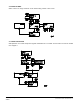
4.6.4 COPY REMOTE TRANSMITTER. This menu is used to copy information from the Master Remote A master remote must be used to include new modules to the network and to reset modules. Transmitter to other remote transmitters, so that they may control units known by the Master Remote Transmitter. A replication of a remote is done as follows: 1. Select “Receive information” on the remote which should receive the information (i.e. the Secondary Remote) 2.
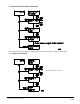
4.6.4.1 SEND INFORMATION There are two options. If the user wants an exact copy of the master remote including groups, scenes, names and so forth “Identical copy” should be selected. If the user wants to create groups, scenes and names from scratch “Only system information” should be selected. When sending is activated the master remote will wait for a secondary remote to respond to its node information broadcast. 4.6.4.2 RECEIVE INFORMATION The flow of the “Receive information” menu is shown below.
4.6.5 RESETTING LAMP AND APPLIANCE MODULES (INCLUDES PLUG IN AND WALL MOUNT) If a switch is to be moved to a new position or added to a new network, it has to be reset before doing so. This is done using this menu. 4.6.6 RESET REMOTE TRANSMITTER The remote transmitter can be reset in two different ways. User data only and factory default. User data only, will only reset groups, scenes and names. The Remote Transmitter will still information about the modules that have been added to the network.
5. OPERATION MODE 5.1 OPERATION DISPLAY When the clock is displayed the remote control is in operation mode. It is from this mode the known units can be controlled through either groups or scenes. 5.1.1 SLAVE REMOTE INDICATION When an underscore is shown in the left bottom corner the remote transmitteris a secondary remote with the limitations mentioned in these instructions. 5.1.2 SCENE INDICATION. From the operation mode press the scene prefix button “S”.
Alternatively, if the group is named, the name will be displayed: The text is displayed for a few seconds or until transmission is complete depending on which of these actions occurs last. If no group of the selected number is defined, the following message will be shown for a few seconds: If for some reason the transmission fails, the following message will be shown until the user presses a key: 5.2.1.2 HOLDING A SPEED BUTTON DOWN.
sequence is as follows: NOTE: If the group on the speed button is unused the user will be presented with the option to include a module when holding down a speed button. This is done with the following display: 5.2.2 CONTROLLING GROUPS USING NAVIGATION KEYS. Another way to access groups is to use the navigation keys (‘<‘,’>’) from operation state. This is the only way to control the groups from 7 to 64.
list. If a group is named the name will be shown instead of the number. In order to switch a group ON or OFF the “OK” button is pressed briefly. If the “OK” button is held down the group will be dimmed and it will be possible to add module to the group being dimmed like mentioned in 5.2.1.2 It looks like this: If a node information frame is detected the flow is like this: 5.2.3 CONTROLLING SCENES Scenes are accessed through the scene prefix button (“S”).
5.2.4 ALL ON/ALL OFF Hitting “all on” button will show this display and “all off” button will result in This display will be shown for the duration of the transmission, which for larger setups can be a while. If the transmission fails either or will be shown until the user presses a key. 6. OTHER INFORMATION The remote transmitter supports 64 modules.
FCC NOTICE Note: This equipment has been tested and found to comply with the limits for a Class B digital device, pursuant to part 15 of the FCC Rules. These limits are designed to provide reasonable protection against harmful interference in a residential installation. This equipment generates, uses, and can radiate radio frequency energy and, if not installed and used in accordance with the instructions may cause harmful interference to radio communications.