
Based Data Acquisition and Control System User's Manual


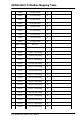
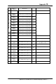


ADAM-5000 I/O Modbus Mapping Table
G-
8
ADAM 5000 Series User’s Manual
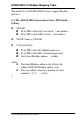
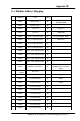
G.5 Address mapping of ADAM-5080 For ADAM-5000
ModBus
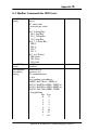
z Slot Start Address :S(word)
OFFSET
bit
HIGH BYTE LOW BYTE
S+0
CH0
S+1
CH0 counter value (Long Word)
S+2
CH1
S+3
CH1 counter value(Long Word)
S+4
CH2
S+5
CH2 counter value(Long Word)
S+6
CH3
S+7
CH3 counter value(Long Word)
15 14 13 12 11 10 9 8 7 6 5 4 3 2 1 0
CH0
Status
flg
S+8
reserve Bit 0 :Counter start/stop
Bit 1:Counter Reset
Bit 2 :Counter Over Flow Flag
CH1
Status
flg
S+9
As Above As Above
CH2
Status
flg
S+10
As Above As Above
CH3
Status
flg
S+11
As Above As Above
S+12~
S+15
RESERVE
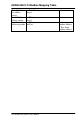
Nots:
1
st
bit: Default ON “1”, available to set ON/OFF to start/stop counting.
2
nd
bit: Normal OFF “0”, only accept a pulse ON signal to clear the
counter and only available when 1
st
bit is OFF.
3
rd
bit: Normal OFF “0”, only turning ON “1” when counter overflow.
Users can write “0”to clear the overflow flag. tuig
priority level
1
st
bit > 2
nd
bit > 3
rd
bit