UPS OPERATING INSTRUCTIONS PROTECT 1. M PROTECT 1.
Thank you for deciding to purchase the PROTECT 1.M UPS from AEG Power Solutions. The following safety instructions are an important part of the operating instructions are will protect you against problems from operating errors and possible dangers.
1 Notes on these Operating Instructions Duty to provide information These operating instructions help you to install and operate the Uninterruptible Power Supply (UPS) PROTECT 1.M as well as its USV modules PROTECT 1.040 and associated external battery units PROTECT 1.M BP (referred to below jointly as PROTECT 1.M) in accordance with its designated use, safely and correctly. These operating instructions contain important information for avoiding dangers.
warranty agreements, service contracts, etc. entered into by AEG or its representatives without prior notice in the event of maintenance and repair work being carried out with anything other than original AEG parts or spare parts purchased from AEG. Handling PROTECT 1.M is designed and constructed so that all necessary steps for start-up and operation can be performed without any internal manipulation of the unit. Maintenance and repair work may only be performed by trained and qualified personnel.
Table of Contents 1 Notes on these Operating Instructions.............................3 2 Introduction.......................................................................7 3 4 5 6 2.1 Product description.....................................................7 2.2 Technical Data..........................................................10 Safety Regulations .........................................................14 3.1 Important Instructions and Explanations ..................14 3.
8 7 Adding/Removing Modules ......................................33 7.1 Active Redundancy ..................................................33 7.2 Installing and Removing UPS Modules....................33 7.2.1 Basic procedure for installing a PROTECT 1.040 UPS module...34 7.2.2 Basic procedure for removing a PROTECT 1.040 UPS module ..34 Operating and Maintenance...........................................35 8.1 9 Operation..................................................................
2 Introduction 2.1 Product description i PROTECT 1.M ("M" for modular structure) is an Uninterruptible Power Supply (UPS) for important loads such as small data centres, servers, network components, telecommunication facilities and the like. The PROTECT 1.M connection to the mains can be either three or one-phase. The load connection, i.e. the UPS output, is always one-phase. The online-/double-converter technology guarantees the highest levels of reliability and performance.
The PROTECT 1.M has been designed for operating up to six UPS modules. Depending on the output power required, the unit is operated in normal mode with between one and six modules installed. These modules can easily be installed, removed or replaced under a very wide range of operating conditions. PROTECT 1.M uses a high-performance communication module to collect information from the individual UPS modules via the internal network within the unit and displays this information on an LC display.
disturbance. Separate battery chargers configured with switch mode power supply technology are responsible for charging or trickle-charging the battery connected in the intermediate circuit. The configuration of these charging rectifiers means the harmonic content of the charging current for the battery is almost zero, which increases the service life of the battery even more. The inverters are responsible for converting the DC voltage into a sinusoidal output voltage.
An integrated, manually operated bypass unit ensures an uninterrupted supply to the connected loads in the case of maintenance and/or service work. The internal electronic part (with the exception of the metal-clad manual bypass) can be disconnected via the mains input miniature circuit breakers.
176 VAC – 264 VAC ±3% (Bypass) Frequency 50 Hz / 60 Hz (Automatic detection) Frequency tolerance range ±4 Hz Current consumption at full load (max.) PROTECT 1.M (system) 44 A (3ph~) or 132 A (1ph~) / 155 A (Bypass) PROTECT 1.040 (module) 7.3 A (3ph~) or 22 A (1ph~) System disturbance factor λ ≥ 0.
Battery Nominal DC voltage (intermediate circuit) 120 Vdc DC window 102 Vdc – 160 Vdc ±1% Trickle charge voltage 137 Vdc ±1% Battery charging current (max.) 3.5 Adc per UPS module Communication Interfaces Shutdown software on CD RS232 (Sub-D9) RS485 (Sub-D9 / RJ45) Additionally: Communication slot for optional expansion cards (e.g. AS/400 / SNMP, etc.) "CompuWatch" for all common operating systems, e.g.
Site altitude Up to 1000 m at nominal output Use more than 1000 m above sea level results in the following reduction in output power: Height (m) 1000 1500 2000 2500 3000 Power 95% 90% 85% 80% 100% Housing colour Blackline Weight: PROTECT 1.M (chassis) PROTECT 1.040 (module) 75 kg 15 kg per module Dimensions W x H x D: PROTECT 1.M (chassis) PROTECT 1.040 (module) 442 mm x 965 mm x 700 mm 405 mm x 87 mm x 530 mm Directives The PROTECT 1.M meets the product standard EN 50091.
3 Safety Regulations 3.1 Important Instructions and Explanations The instructions for operation and maintenance as well as the following safety regulations must be complied with to ensure the safety of personnel as well as to ensure the continued availability of the unit. All personnel installing/dismantling, starting up, operating or servicing the units must be familiar with and observe these safety regulations.
♦ Disconnect the unit from the power supply ♦ Secure the unit against being switched back on ♦ Verify that the unit is disconnected from the power supply ♦ Earth and short-circuit the unit ♦ Provide protection by covers or barriers for any neighbouring live parts 3.3 Qualified Personnel The PROTECT 1.M may only be transported, installed, connected and serviced by qualified personnel who are familiar with the pertinent safety and installation regulations.
The output can be live, even when the UPS is not connected to the mains supply! For health and safety reasons, the unit must be earthed correctly! The PROTECT 1.M may only be operated with or connected to three-phase or AC voltage power systems with protective grounding using a mains connection cable with PE conductor that has been tested according to German standards (VDE). Risk of burning! The battery has powerful short-circuit currents.
UPS must be absolutely dry prior to start-up. As a result, leave it to acclimatise for at least two hours. ♦ Never connect the mains input and the UPS output! ♦ Ensure that no fluids or foreign bodies can penetrate the housing! ♦ Do not block the air vents of the unit! Make sure, for example, that children do not insert any objects in the ventilation openings! ♦ Do not connect household appliances such as hairdryers to the UPS! Also take care when working with motor loads.
Batteries can cause electric shocks and high short-circuit currents. Therefore, take the following safety precautions when working with batteries: ♦ Take off watches, rings and other metallic objects! ♦ Only use tools with insulated handles! 3.
4 Set-up 4.1 Unpacking and Inspection The unit has been completely checked and inspected. Although the device has been packed and shipped with the usual degree of care, damage during transport cannot be ruled out completely. i Claims for damage during transport must always be made with the transport company! Check the shipping container for damage on arrival.
2. Remove the foam from the unit (see Fig. 2); remove the plastic wrapping; 3. Remove the lower module and the foam from the frames (see Fig. 3); 4. Now, with the assistance of at least one other person, carefully lift the system cabinet off the pallet and move it to the installation location. Fig. 1 Fig. 2 Fig.
4.2 Transport to Installation Site The PROTECT 1.M is equipped with transport rolls for easy transport to the intended installation site. It is recommended to install the UPS where: ♦ The connection work can be conveniently carried out; ♦ There is enough space for proper operation and, if necessary, for periodic and extraordinary maintenance work; in this regard, the connection cables should be long enough to move the UPS (to open the UPS if necessary) without having to switch it off.
4.3 Set-Up Note the following points when setting up the UPS system and its external battery units (special accessories): ♦ The contact surface must be smooth and level. It must also be sufficiently strong and sturdy to avoid vibration and shocks. ♦ Make sure that the mounting is able to support the weight, especially in conjunction with external battery units (special accessories). ♦ Set up the units so that adequate air circulation is assured.
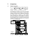
5 External View 5.1 Front and Rear View of PROTECT 1.M (chassis) LED indicators LC display Keys for UPS menu navigation System On/Off Communication port Communication module UPS modules PROTECT 1.040 Slot cover caps with intake air channelling Front view with slot covers mounted Communication slot RS485 RS232 RS485 RS485 Front view with slot covers removed Cover for mains input switch Cover with electronic interlocking for manual bypass switch Connection terminal cover Rear view of PROTECT 1.
5.2 Front/Rear and 3D View PROTECT 1.040 (UPS module) Handles with latching for easy removal or insertion of a PROTECT 1.040 UPS module Fans 5.3 Front view RS232 Fans Blade-connect male Rear view Orientation markings for optimum displacement of the centre of gravity when holding a PROTECT 1.
Front and Rear View (communication module) Blade-connect Co nnec tor REAR VIEW Rear view Handle Ha nd le LCD port Communication c om m unic a tion for connecting the p ort LC display SIDE VIEW FRONTVIEW Front view 5.
5.5 Display Panel 1. "Normal": The green LED lights when the UPS is supplying the loads with voltage via the inverters (normal operation). 2. "On Battery": The yellow LED lights when the UPS is supplying power from the battery. 3. "Bypass": The yellow LED lights when the UPS is supplying the loads with mains voltage from public utility's mains. 4.
6 Installation 6.1 Installation Notes 1. This unit must be installed by qualified personnel in accordance with the locally applicable electrical regulations. 2. The PROTECT 1.M uses fans for cooling, which means sufficient ventilation must be provided at the installation location (see also chapter 6.2: Installation area). 3. A battery system with a nominal DC voltage of 120 Vdc is required as the external battery for the PROTECT 1.M.
b. Connection with three-phase input Note: If using three-phase mains connection, make sure the phase sequence is correct. The UPS cannot start up if the phase sequence is wrong, and an alarm will sound. At the same time, "Phase sequence error" appears on the LC display. Make sure the neutral conductor is connected correctly as well. 5. Installation clearances > 30cm Mo re th ar e 80 cm Mo re th ar e 30 cm A gap of at least 80 cm is required in front of the PROTECT 1.
5.
i If you are using fuse load break switch for mains fusing, please select miniature circuit breakers with "D" characteristic. Route wires individually to guarantee reliable strain relief. Preferably use special rubber-insulated wire NSGAÖU or NSGAFÖU, NYY or Radox 4GKW-AX.
6.2 Set-up and Installation of the Modules 1. To set up the unit, position it in its installation location and use a spanner to turn the heightadjustable feet until they reach the floor. The feet are located at the four corners of the baseplate. Locking foot Bra ke pad 2. 3. Push the communication module into the top lefthand corner of the uppermost slot (see illustration above). Push all PROTECT 1.
Hold the UPS module firmly at the sides when pushing it in. Your thumbs should make contact with the orientation marks on the UPS module (see illustration below). 4. Install the slot cover caps: Insert the slot cover caps from bottom to top over each individual slot. To ensure optimum cooling of the individual UPS modules, continuous operation is only permitted with the slot cover caps in place. 5.
7 Adding/Removing Modules 7.1 Active Redundancy n+x technology is one of the most reliable configurations. "n" represents the minimum number of PROTECT 1.040 UPS modules that requires the total power; "x" represents the number of redundant PROTECT 1.040 UPS modules, i.e. the number of fault-tolerant modules that the system can handle at the same time. Assume the apparent output power to be achieved is 15 kVA, for example. One module of the PROTECT 1.M delivers 4 kVA.
7.2.1 Basic procedure for installing a PROTECT 1.040 UPS module 1. Remove the slot cover cap from the rack in which the UPS module is going to be installed. 2. Grip the UPS module at the sides with both hands. The black dots on the top of the UPS module serve as orientation marks for where to position your thumbs in order to have the centre of gravity in the optimum position. Slowly and carefully push the module into the housing slot. Make sure that the warning notice is facing upwards. 3.
8 Operating and Maintenance 8.1 Operation 1. 2. 3. 4. 5. Make sure that the phase sequence is correct if you are using a three-phase mains connection (L1, L2, L3). If you are using a single-phase mains connection, make sure that phase L1 has been selected and correctly connected to the UPS. Furthermore, make sure that the neutral conductor has been connected properly and that the system is adequately earthed. Check the polarity of the battery system.
4) Press ▼ for the following information 3) Press ESC LOAD: 0% BATT: 137 I / P VOLT: 232 232 231 O / P VOLT: 0 O / P FREQ: 0.0Hz STATUS: NO OUTPUT OUTPUT PARAMETER RN SN TN VOLT: 0V CURR: 0A FREQ: 0.0Hz Note: When the mains is connected for the first time, the UPS does not output any voltage (Figs. correspond to this status) 5) Press ▼ again for the following information 6) Press ▼ again for the following inform. INPUT PARAMETER RN SN TN VOLT: 232 232 231 FREQ: 50.
8.1.1 Start-up 1) Switch on 2) Press the ↵ / Return key 3) Press the ▼ key CONFIRM TURN UPS ON Æ NO, CANCEL YES, CONFIRM Æ UPS ON SETUP INQUIRE 4) Once again, press the ↵ / Return key LOAD: 0% BATT: 136 I / P VOLT: 232 232 231 O / P VOLT: 230 O / P FREQ: 50.0Hz STATUS: 3 PHASE I / P UPS IS TURNING ON PLEASE WAIT… 8.1.
3) Switch-off option 1: Load supply via bypass "SWITCH TO BYPASS" 4) Switch-off option 2: Load supply directly off "TURN OFF OUTPUT" CONFIRM SWITCH TO BYPASS Æ NO, CANCEL YES, CONFIRM CONFIRM WARNING: OUTPUT OFF Æ NO, CANCEL YES, CONFIRM 5) Select "YES, CONFIRM" and press the ↵ / Return key again 8.1.
3) Press the ↵ / Return key at the "PHONE" item, for example RETAILER PHONE: XXXXXXXXXXXX XXXXXXXXXXXX 8.1.
5) Select SETUP, e.g. REDUNDAN and 6) E.g. if the number of redundant modules is 0, … press ↵ / Return SETUP REDUNDANCE TOTAL NUM: 3 ÆREDUN NUM: 1 MAX POWER CURRENT SETTING: 8kVA/5.6kW WARNING: CURRENT SETTING IS NO REDUNDANCY, OK? YES Æ NO The redundancy setup applies after the Setup menu is exited, i.e. the UPS displays "Overload" if the power is more than 8 kVA / 5.6 kW. 7) Switch on the PROTECT 1.
8.2 Maintenance 1. 2. 3. Maintenance of the UPS and battery replacement should be performed by well trained expert personnel. Batteries that have not been used for some time must be charged up every three months at normal ambient temperature and every two months if the ambient temperature is high. The three switches on the back, from top to bottom, are as follows: Mains fuse-switch disconnector, manual service bypass switch and output switch.
8.3 Shutdown and UPS Management Software The "CompuWatch" software specially developed for these purposes by AEG continuously checks the mains supply and the UPS status. In conjunction with the "intelligent" UPS, this guarantees the availability of the EDP components as well as the data security. The "CompuWatch" shutdown software supports different operating systems, e.g.
9 Communication Interfaces The PROTECT 1.M has RS232 and RS485 interfaces as well as an expansion slot: As external connections, it is possible to use either an AS400 card (optional) or an SNMP/ SNMP PRO card (optional) for the expansion slot. 1. The standard RS232 interface is for the "CompuWatch" control software. 2. The RS485 connection makes it possible to monitor and control all the functions of the UPS from a remote location. 3.
10 Troubleshooting and Fault Rectification If error messages are displayed, please refer to the following table in order to localise the fault that has occurred and to find information about what measures to take to rectify the fault. If you cannot resolve the problem(s), please contact the Service Center (see page 5 "Hotline"). 1. Check whether the UPS connection, and specifically the mains connection, has been made correctly. 2.
11 Reference Table for the Display and UPS Operating Problems 11.1 Normal operation Operating status / Warning signal LC displays Notes Fault (Fault) Bypass (Fault) Battery (On Battery) Normal (Normal) Operating problems LED indications Mains in tolerance range None Mains not in tolerance, i.e. batt. operation 1 acoustic signal every 4s "utility power is abnormal" 11.
11.4 Warning Signal if Battery System Not Connected, e.g. battery fuse failure Operating status / LC displays Notes Bypass mode 1 acoustic signal every 4 s "UPS is not connected to the battery" Check battery system; poss. fuse fault? Normal mode 1 acoustic signal every 4 s "UPS is not connected to the battery" Check battery system; poss. fuse fault? Fault (Fault) Bypass (Fault) Battery (On Battery) Normal (Normal) Warning signal Operating problems LED indications 11.
11.
12 Minimum Number of Battery Packs Batteries with different capacity have specific charging and discharging characteristics. Standard configurations have been defined in order to make optimum use of the service life. The hatched part shows the permitted configurations.
The following tables show the achievable standby times according to the UPS expansion level and capacity utilisation as well as depending on the optional battery cabinet units that are connected ex-works: 49
13 List of terms 13.1 Technical terminology DC/DC booster Circuit technology for increasing a DC voltage to a higher voltage level SBS Static Bypass Switch Appliance protection Term from overvoltage technology Classic mains overvoltage protection consists of lighting surge arrester (class B), overvoltage protection (class C) and, finally, the so-called appliance protection (class D) - see also the http://www.phoenixcontact.
Notes 52
Notes 53
Notes 54
Notes 55
Guarantee Certificate Type: …….……………….…...................................................... Unit number: ….………….…..……………................................ Date of purchase:………………...........……………………........ Dealer stamp / signature Errors and changes excepted.