Clamp-on Ground Tester Model 6416 USER MANUAL ENGLISH ® www.aemc.
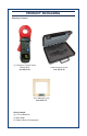
PRODUCT PACKAGING Shipping Contents: (1) Clamp-on Ground Tester Model 6416 Cat. #2141.01 5W Calibration Loop Cat. #2141.51 Also Included: (4) 1.5V AA Batteries (1) Wrist Strap (1) Safety Sheet (20 languages) Hard Accessory Case Cat. #2141.
Statement of Compliance Chauvin Arnoux®, Inc. d.b.a. AEMC® Instruments certifies that this instrument has been calibrated using standards and instruments traceable to international standards. We guarantee that at the time of shipping your instrument has met its published specifications. An NIST traceable certificate may be requested at the time of purchase, or obtained by returning the instrument to our repair and calibration facility, for a nominal charge.
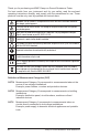
Thank you for purchasing an AEMC Clamp-on Ground Resistance Tester. For best results from your instrument and for your safety, read the enclosed operating instructions carefully and comply with the precautions for use. These products must be only used by qualified and trained users. WARNING, risk of DANGER! The operator must refer to these instructions whenever this danger symbol appears. CAUTION! Risk of electric shock. The voltage at the parts marked with this symbol may be dangerous.
PRECAUTIONS FOR USE This instrument and its accessories comply with safety standards EN 61010-1, EN 61010-030, and EN 61010-2-032 for voltages of 600V in Category IV at an altitude of less than 2000m with a pollution degree of not more than 2. Failure to observe the safety instructions may result in electric shock, fire, explosion, and destruction of the instrument and of the installations.
Table of Contents 1. INTRODUCTION..............................................................................................6 1.1 Receiving Your Shipment......................................................................6 1.2 Ordering Information..............................................................................6 1.2.1 Replacement Parts....................................................................6 2. PRODUCT FEATURES................................................................
5.8 Alarm Management.............................................................................25 5.8.1 Voltage Alarm..........................................................................25 5.8.2 Current Alarm..........................................................................25 5.8.3 Impedance Alarm....................................................................25 5.8.4 No Alarm Detection.................................................................26 5.8.5 Priority of the Alarms..
1. INTRODUCTION 1.1 Receiving Your Shipment Upon receiving your shipment, make sure that the contents are consistent with the packing list. Notify your distributor of any missing items. If the equipment appears to be damaged, file a claim immediately with the carrier and notify your distributor at once, giving a detailed description of any damage. Save the damaged packing container to substantiate your claim. 1.2 Ordering Information Clamp-on Ground Resistance Tester Model 6416........................
2. PRODUCT FEATURES 2.1 Description The Clamp-on Ground Resistance Tester Model 6416 measures grounding electrodes and grid resistance without the use of auxiliary rods. Clamp-on ground resistance testers can be used in multi-grounded systems without disconnecting the ground system under test. The Model 6416 simply clamps around the ground conductor or rod and measures the resistance to ground.
2.2 Features ■■ Simple and fast clamp-on operation - no leads, no auxiliary rods or spacing requirements -- Ammeter: Current measurements from 0.2mA to 40A. -- Loop ohmmeter: Measurement of loop impedances from 0.01 to 1500W. The ohmmeter function makes allowance for the presence of inductances in the loop, making impedance measurements more accurate at low values. -- Contact voltage: The contact voltage is determined by calculating the product of the loop impedance and leakage current.
2.4 Display The Model 6416 is equipped with a 152-segment OLED (organic light-emitting diode) display. This OLED technology results in a thinner, lighter, sharper, higher contrast display compared to LCD displays. 21 20 19 18 17 16 15 14 1 13 2 3 4 12 5 6 7 8 9 10 11 Figure 2-1 Item Description 1 Indicates selection of Advanced mode. 2 In Advanced mode, this indicates when the inductive component is negligible with respect to the resistive component.
9 10 11 12 Alarm threshold high/low indicator (operational use or configuration): ▲ Alarm threshold high indicator. AL Alarm threshold adjustment mode or Alarm function. ▼ Alarm threshold low indicator. Alarm threshold display: -- Display of one of the alarms (1000-count display) with units. -- These three digits are also used when configuring the time display mode. (A for A.M., P for P.M. or 24H) in SET-UP (see § 4.4, menu #8). Unit of the alarm displayed.
2.5 Control Features 1 2 600V CAT IV 40A SET-UP MR 3 OFF 4 5 8 A HOLD MEM 9 6 7 Figure 2-2 1. Head Assembly: Consists of two individually shielded magnetic cores 2. Guard: Safety guard; do not place hands above this guard 3. Lever: Opens or closes the jaws 4. : Toggles display backlight ON/OFF 5. MEM: Stores measurements into memory 6. ►: Navigates and validates measurement displays 7. OLED Display: Crisp, clean and bright display 8.
2.6 Audible Signals There are four audible signals: Type Duration Low-pitched High-pitched Short Description Normal use (button pressed). Permanent High/Low alarm threshold (Ω, A) triggered. Short Abnormal use (for example, memory full). Permanent Alarm threshold (V) exceeded. Audible signals can be enabled or disabled in SET-UP (see § 4.4, menu #2). symbol indicates: The Description Visible Not Visible Buzzer enabled; an alarm or a button press causes an audible signal to be emitted.
2.8 Button Functions Button Description • When the rotary switch is set to Ω+A or A: Increases the brightness of the display, making it easier to read the display in an environment with strong background illumination. Highlighting activated for 30 seconds. • When the rotary switch is set to SET-UP or MR: Serves as the ▲ arrow when browsing in the menus and values. The brightness of the display does not change when device is set to SET-UP or MR.
3. PRINCIPLE OF OPERATION Typically, a grounded distribution system can be simulated by the basic circuit shown in Figure 3-1 or an equivalent to the diagram shown in Figure 3-2. If voltage (V) is applied to any measured grounding electrode Rx through a special transformer; current (I) flows through the circuit, thereby establishing the following equation: V = Rx + I Σ 1 n i=1 1 Ri where, usually Rx » Σ 1 n i=1 1 Ri Therefore, V/I = Rx is established.
Rx R1 Rn-1 Rn Figure 3-2 Clamp-on Ground Resistance Tester Model 6416 15
4. SET-UP Turn the rotary switch to the SET-UP position. 4.1 Menu Items The SET-UP position gives access to the following options to set user defined parameters for instrument configuration: No. Function 1 Erases stored measurements. 2 Enables/disables the buzzer. 3 Enables/disables Auto Power OFF 4 Sets the impedance alarm threshold (W). 5 Sets the voltage alarm threshold (V). 6 Sets the current alarm threshold (I). 7 Sets the date. 8 Sets the time.
4.3 Selecting a Specific Menu Use the buttons as follows to select a specific menu item: Button Action ▲ Move up in the menu tree. ▼ Move down in the menu tree. ► Select the menu displayed or return to the previous menu. NOTE: When changes have been made in one of the SET-UP menus, the changes can be cancelled by turning the rotary switch to a position other than SET-UP, provided that there has not been a return to the main menu (by pressing ►). 4.
Menu # 4 Indication AL. Ω Function Setting the Impedance Alarm Threshold (Ω): ■ Enter the menu by ►. AL. Ω blinks. ■ Press ▲ or ▼ to select the state of the alarm: -- : Disabled. -- : Enabled for a measurement exceeding the threshold. -- : Enabled for a measurement below the threshold. ■ Validate by ►. Setting the Alarm Value: ■ Press ▲ or ▼ to select the impedance alarm threshold (Figure 2-1, item #11). ■ Validate and return to the previous menu by ►. 5 AL.
Menu # 7 Indication dAtE Function Setting the Date: ■ Enter the menu by ►. dAtE blinks. ■ Press ▲ or ▼ to select the year. Validate by ►. ■ Press ▲ or ▼ to select the month. Validate by ►. ■ Press ▲ or ▼ to select the date. ■ Validate and return to the previous menu by ►. NOTE: In some locations the order of the date values is displayed as Year, Date, Month. 8 9 10 HOUR Setting the Time: ■ Enter the menu by ►. HOUR blinks. ■ Press ▲ or ▼ to select the AM/PM (A. or P.
Menu # Indication Function Enabling/Disabling the AUTO-HOLD Mode: ■ Enter the menu by ►. HOLd blinks. ■ Press ▲ or ▼ to switch the AUTO-HOLD mode to active or inactive. 11 HOLd -- AUTO-HOLD Mode Disabled: Only the icon is displayed. -- AUTO-HOLD Mode Enabled: The and icons are displayed. ■ Validate and return to the previous menu by ►. 12 VER Displaying the version number ■ Enter the menu by ►. ■ The version number is displayed. ■ Return to the previous menu by ►.
5. OPERATION 5.1 Inserting the Batteries ■ Unclamp and remove the instrument from any connections and turn the rotary switch to the OFF position. ■ Use a Phillips head screwdriver to unscrew the two attachment screws and remove the battery compartment cover. + + Figure 5-1 + + ■ Remove the old batteries and replace them with four new batteries (LR6, AA, 1.5V), observing the polarities. ■ Close the battery compartment cover and tighten the two screws. ■ Check for the proper operation of the device.
5.3 Display Example Figure 5-2 shows a typical display upon first use, with the device set to Ω+A. In this example, the measured current is 30.0mA and the impedance is 7.9W. The buzzer is active and the memory is empty. NOTE: This display corresponds to the device in Standard mode. In Advanced mode, two additional screens are available (see § 6.1.2.2). Figure 5-2 Figure 5-3 shows a display, upon first use, with the device set to A. In this example, the current measured is 30.0mA.
5.5 Turning the Instrument OFF The instrument can be turned OFF in two ways: ■ Manually: Turn the rotary switch to OFF. ■ Auto Power OFF: This function activates after 5 minutes of no activity (no button press, no change of switch setting, and no opening of the jaws). -- Fifteen seconds before Auto Power OFF, a short audible signal is emitted and the display blinks once a second. Auto Power OFF can be disabled in SET-UP (see § 4.4, menu #3). The symbol is then displayed. 5.
All calculated impedance and/or current values, together with the values accessible in the secondary screens in Advanced mode, are stored as soon as the MEM button is pressed, such as: ■ ■ ■ ■ ■ ■ Current measurement (A) Measurement of the resistance, inductance, and impedance (Z) Contact voltage measurement (V) Present configuration of the clamp Sequence number of the record Time and date of the record The display indicates the sequence number of the last measurement recorded, or 0 if the memory is empty
5.8 Alarm Management The device has three distinct alarms that can be configured. NOTE: The (W, V, A) alarm thresholds can be configured in SET-UP (see §4.4). 5.8.1 Voltage Alarm ■ If the voltage (product ZxI) exceeds the threshold set, the alarm symbol and the alarm threshold blink. ■ If the buzzer is active, a high-pitched audible warning signal is emitted. Figure 5-4 5.8.2 Current Alarm ■ If the current exceeds the threshold set, the alarm symbol and the alarm threshold blink.
5.8.4 No Alarm Detection If no alarm is activated, the alarm icons are not displayed. ■ When no alarm is triggered, the alarm threshold is displayed, along with the direction of triggering ( , ) of the impedance, voltage, or current alarm. Figure 5-7 5.8.5 Priority of the Alarms If several alarms are triggered simultaneously, a priority rule determines the display and the corresponding sound: ■ The voltage alarm has priority because it concerns the user’s safety.
6. MEASUREMENT MODES Rotary Position Ω+A 6.1 6.1.1 Standard Mode Selection of Standard mode is performed in the SET-UP (see § 4.4, menu #9). In Standard mode, only one measurement screen is available. The clamp measures the loop impedance (Ω) (at the fixed frequency of 2083Hz) and the leakage current. NOTE: Since the measurement frequency is audible, the operator hears a beeping signal. This is neither an operating fault nor an alarm, and it cannot be eliminated.
6.1.1.2 Measurement Results Once the measurement has stabilized, the display indicates: - The leakage current. - The impedance of the loop at the frequency of 2083Hz. The impedance is measured only if the leakage current is less than 10A. In the 10 to 40A range, only the current is displayed; the NOISE symbol blinks and the impedance is replaced by dashes. Figure 6-1 To store the measurement into memory, press the MEM button (see § 5.7.2).
6.1.2.2 Measurement Results First Screen: Once the measurement has stabilized, the display shows the first screen, which indicates: - The leakage current (I). - The loop impedance (Z) referenced to the chosen frequency. The impedance is measured only if the leakage current is less than 10A. In the 10 to 40A range, only the current is displayed; the NOISE symbol blinks and the impedance is replaced by dashes.
6.1.3 General Information This information is displayed in both Standard and Advanced modes. PRODUCT ZxI GREATER THAN 50V - The blinking NOISE symbol is displayed. - The impedance blinks. - The hazardous voltage symbol blinks. Figure 6-5 IMPEDANCE GREATER THAN 1500Ω In this case: - The impedance display indicates O.R (Over Range). Figure 6-6 LEAKAGE CURRENT DISTURBANCE If the current is greater than 5A, or if it is significantly disturbed: - The blinking NOISE symbol is displayed.
6.2 Rotary Position (A) In the A position, the clamp measures the electrical current, independently of any ground/earth measurement. If desired, configure the current alarm threshold as desired (see §4.4, menu #6). 6.2.1 Making a Measurement ■ Turn the rotary switch to the A position, and wait several seconds while the instrument performs internal calibration. ■ Clamp around the conductor to be measured. If the clamp is incorrectly closed, the icon is displayed.
6.3.1.1 Data Displayed in Standard Mode The last measurement is displayed. The MR symbol and the sequence number of the record being recalled are also displayed. Figure 6-11 illustrates an impedance plus a current measurement (Ω+A setting). Figure 6-11 The stored values are displayed as they were when recorded: same display range, alarm states, NOISE signal, battery condition, etc. However, the audible alarms are not reproduced; only the AL symbol and the alarm threshold blink.
6.3.1.2 Data Displayed in Advanced Mode First Screen: - The last measurement is displayed, namely the impedance referenced to the chosen frequency. - The MR symbol and the sequence number of the record being recalled are also displayed. - Figure 6-14 illustrates an impedance and current measurement. Figure 6-14 - Press ► to display the next screen. Second Screen: - Figure 6-15 illustrates a contact voltage measurement (product ZxI). - Press ► to display the next screen.
7. SPECIFICATIONS 7.1 Reference Conditions Influencing Parameters Ambient temperature Relative humidity Battery voltage Magnetic field Electric field Operating position Position of the conductor in the clamp Reference Values 73°F ± 5°F (23°C ± 3°C) 50% RH ±10% 6V ± 0.2V < 40A/m DC (no AC field) < 1V/m Clamp horizontal Centered No adjacent conductors carrying current within 10cm > 10cm Non-inductive resistance (20Ω for the voltage measurement) Frequency 50/60Hz Level of distortion < 0.
Measurement Frequency: 2083Hz Frequency Selection: Choice of 50, 60, 128, or 2083Hz for the impedance calculation Maximum overloads: - permanent current 100A maximum (50/60Hz) - transient current (<5s) 200A (50/60Hz) 7.2.2 Loop Inductance Measurement Measurement Range 10 to 100µH 100 to 500µH 7.2.3 Resolution 1µH 1µH Accuracy ±5% ±1µH ±3% ±1µH Contact Voltage (Touch Voltage) Contact Voltage Function: Value calculated as the product of the loop impedance by the leakage current. Measurement Range 0.
7.2.5 Power Supply ■■ 4x1.5V LR6 (AA) alkaline batteries or 4 NiMH batteries ■■ Battery Consumption: 140mA approx ■■ Battery Life: 12 hours, or 1440 30-second measurements approx NOTE: Extreme environmental conditions may interfere with the internal microprocessor. Simply disconnecting the battery may be enough to eliminate this malfunction. 7.
7.5 Safety The instrument complies with IEC 61010-1, and IEC 61010-2-032 for the following: ■■ Measurement inputs and enclosure: 600V CAT IV 5003266 Conforms to UL Std. UL 61010-1 Conforms to UL Std. UL 61010-2-032 Cert. to CAN/CSA Std. C22.2 No. 61010-1 Cert. to CSA Std. C22.
8. MAINTENANCE Use only factory specified replacement parts. AEMC® will not be held responsible for any accident, incident, or malfunction following a repair done other than by its service center or by an approved repair center. 8.1 Cleaning Disconnect anything connected to the device and set the switch to OFF ■■ Use a soft cloth lightly moistened with soapy water, taking care not to touch the contacts inside the clamp. Wipe with a moist cloth and then completely dry with a dry cloth.
8.3 Repair and Calibration To ensure that your instrument meets factory specifications, we recommend that it be sent to our factory Service Center at one-year intervals for recalibration, or as required by other standards or internal procedures. For instrument repair and calibration: You must contact our Service Center for a Customer Service Authorization Number (CSA#). This will ensure that when your instrument arrives, it will be tracked and processed promptly.
8.5 Limited Warranty The Clamp-on Ground Tester Model 6416 is warranted to the owner for a period of two years from the date of original purchase against defects in manufacture. This limited warranty is given by AEMC® Instruments, not by the distributor from whom it was purchased. This warranty is void if the unit has been tampered with or abused, or if the defect is related to service not performed by AEMC® Instruments. Full warranty coverage and product registration is available on our website at www.
Notes:
08/18 99-MAN 100398 v9 Chauvin Arnoux®, Inc. d.b.a. AEMC® Instruments 15 Faraday Drive • Dover, NH 03820 USA • Phone: (603) 749-6434 • Fax: (603) 742-2346 www.aemc.