
User Guide

10 Clamp-on Ground Resistance Tester Model 6416
9
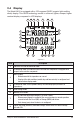
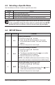
Alarm threshold high/low indicator (operational use or configuration):
▲ Alarm threshold high indicator.
AL Alarm threshold adjustment mode or Alarm function.
▼ Alarm threshold low indicator.
10
Alarm threshold display:
- Display of one of the alarms (1000-count display) with units.
- These three digits are also used when configuring the time display mode.
(A for A.M., P for P.M. or 24H) in SET-UP (see § 4.4, menu #8).
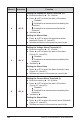
11
Unit of the alarm displayed. The alarm can be defined on a resistance impedance,
voltage, or current, depending on the measurement chosen (W+A or A).
- A: Current measurement alarm.
- W: Resistance measurement alarm.
- V: Voltage measurement alarm.
12
Unit of the central measurement display:
- V: Contact voltage measurement unit.
- W: Impedance measurement unit. Symbol used for impedances at the
measurement frequency, for impedances referred to the network frequency, or
for the resistive component.
13
Unit of the top measurement display:
- mH: Loop inductance measurement unit.
- mA or A: Current measurement unit.
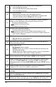
14
Upper display: 4000-count current measurement and 500-count loop inductance
measurement (Advanced mode).
15
Battery charge indicator:
- Not displayed: Batteries charged.
- Blinking: Batteries low. The device remains functional, but the batteries will
have to be replaced soon.
- Steady: Batteries discharged. The display indicates Lo bat. It is not possible to
make measurements, read records, or configure parameters.
16
Continuous operation of the clamp (Auto Power OFF disabled).
Selection of Auto Power OFF mode is made in SET-UP (see § 4.4, menu #3).
17
Symbol indicating incorrect closing of the clamp; measurements cannot be made
in this case. If the AUTO-HOLD mode is activated, the HOLD icon blinks and the
measurement is frozen. Selection of AUTO-HOLD mode is made in SET-UP (see § 4.4,
menu #11).
18
Symbol indicating the presence of disturbance (current) in the loop, which
compromises the accuracy of the impedance measurement.
19
Indicates that the main display shows the date (when the rotary switch is set to MR
or SET-UP).
20
Indicator of freezing the measurement display when the HOLD button is pressed or
while in the AUTO-HOLD mode.
21
Display of the buzzer’s active state; the icon is not shown when the buzzer is inactive.
Selection of the buzzer operating mode is made in SET-UP (see § 4.4, menu #2).