
User Guide

14 Clamp-on Ground Resistance Tester Model 6416
3. PRINCIPLE OF OPERATION
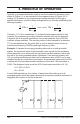
Typically, a grounded distribution system can be simulated by the basic circuit
shown in Figure 3-1 or an equivalent to the diagram shown in Figure 3-2. If
voltage (V) is applied to any measured grounding electrode Rx through a
special transformer; current (I) ows through the circuit, thereby establishing the
following equation:
V
I
= Rx +
1
Σ
n
i=1
1
Ri
Rx »
1
Σ
n
i=1
1
Ri
where, usually
Therefore, V/I = Rx is established. If I is detected and measured with V kept
constant, the measured grounding electrode resistance Rx can be obtained.
A signal is fed to a special transformer via a power amplier from a 2403Hz
constant voltage oscillator. The resulting current is then sensed by a detection
CT (current transformer). An active lter is used to dampen earth current at
commercial frequency (50/60Hz) and high-frequency noise.
Example: If clamped around any grounding electrode in a multi-grounded
system, the measured value of the electrode under test will be the resistance
of that particular rod in series with the equivalent parallel resistance value that
the rest of the multi-grounded system represents. If an electrical system had
101 grounding electrodes and each had a resistance value of 25W, and it were
clamped around any electrode in the system, the measured value would be 25W
in series with the equivalent parallel resistance of the other 100 electrodes or
0.25W. The displayed value would be 25.2W (instrument resolution to 0.1W).
V/I = 25W + 0.25W
Rx = 25.2W
In most eld applications, the number of electrodes that make up a multi-
grounded system would be higher; therefore the equivalent parallel resistance is
negligible with respect to the rod under test.
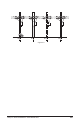
I
V
Rx R1 R2 Rn-1 Rn