
User Guide


22 Clamp-on Ground Resistance Tester Model 6416
5.3
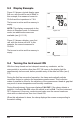
Display Example
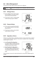
Figure 5-2 shows a typical display upon
first use, with the device set to Ω+A. In
this example, the measured current is
30.0mA and the impedance is 7.9W.
The buzzer is active and the memory is
empty.
NOTE: This display corresponds to the
device in Standard mode. In Advanced
mode, two additional screens are
available (see § 6.1.2.2).
Figure 5-3 shows a display, upon first
use, with the device set to A. In this
example, the current measured is
30.0mA.
The buzzer is active and the memory is
empty.
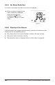
5.4 Turning the Instrument ON
With the clamp closed and not clamped around any conductor, set the
rotary switch to a position other than OFF. All icons on the display light for
approximately two seconds, before possible entry of the date and time (see §
5.2).
During the rst few seconds of operation, the clamp automatically adjusts
correction factors to optimize the impedance measurement. This correction
makes it possible to allow for the variations of the measurement head air gap that
may occur in some temperature and humidity conditions.
During this adjustment, the screen displays CAL GAP. If the clamp detects a
problem, it indicates Err CAL when the switch is set to Ω+A. Turn the instrument
OFF, disconnect it from any conductor and make sure the sensor heads are
clean with no obstructions, then turn it back ON.
When this adjustment is done, the clamp displays the screen corresponding to
the switch setting.