AGA ELECTRIC (EC-LMV & EE-LMV) COOKER - (EXTENDED OVEN VENT) OWNERS MANUAL Comprising Installation & Users Instructions Remember, when replacing a part on this appliance, use only spare parts that you can be assured conform to the safety and performance specification that we require. Do not use reconditioned or copy parts that have not been clearly authorised by AGA.
CONTENTS SECTION PAGE INSTALLATION SECTION 3 INSTALLATION 3-5 ELECTRICAL 5 INSTRUCTIONS 6 ELECTRICAL TEST PROCEDURE 6 OVEN VENT PIPE CONNECTION OPTIONS 7 OVEN VENTING SYSTEMS 8-9 USER GUIDE 10 HEALTH & SAFETY 10 THE AGA COOKER 11 OPERATING THE AGA 12 THE HEAT INDICATOR 13 THERMOSTAT CONTROL 13 POWERED OVEN VENTING 13 GUIDE TO AGA COOKING 14 FITTING OF OVEN SHELVES 15 REMOVAL OF OVEN SHELVES 15 CARING AND CLEANING FOR THE AGA 16 SERVICING 16 2
INSTALLATION SECTION Consumer Protection As responsible manufacturers we take care to make sure that our products are designed and constructed to meet the required safety standards when properly installed and used. IMPORTANT NOTICE: PLEASE READ THE ACCOMPANYING WARRANTY Any alteration that is not approved by AGA could invalidate the approval of the appliance, operation of the warranty and could also affect your statutory rights.
The top of the hearth must be of non-combustible material thickness of 12mm. The wall behind the cooker must be of non-combustible material for a minimum thickness of 25mm. If the oven vent pipe passes through combustible material, there must be an airgap of at least 25mm around the pipe preferably wrapped with insulation material. The appliance oven venting pipe can be achieved up to a maximum length of 6 metres, through an outside wall or unused flue etc. Great care must be taken in all-timber houses.
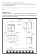
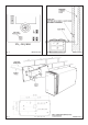
EE-LMV MODEL * THIS HOLE IF REQUIRED FOR OVEN VENT PIPE IS TO BE CUT ON SITE IN THE LEFT OR RIGHT HAND SIDE PANEL. A Fig. 1A B C D F G H mm 1487 889 851 679 1330 756 1125 K L 3 M N R T V W X Y Z 698 484 816 116 52 790 873 55 699 662 ELECTRICAL WARNING: THIS APPLIANCE MUST BE EARTHED. THIS APPLIANCE IS DESIGNED FOR THE VOLTAGE STATED ON THE RATING PLATE, WHICH IS SITUATED BEHIND THE LOWER LEFT HAND DOOR.
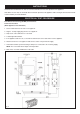
INSTRUCTIONS Hand this Owners Manual to the User for retention and instruct in the safe operation of the appliance. Also advise the user that, for continued efficient and safe operation of the appliance that servicing is carried out at intervals recommended by the AGA distributor. ELECTRICAL TEST PROCEDURE Final Electrical Test using (CLARE) and Flash Test Flash Test Procedure (Earth Appliance Test Simulation) 1. Select 1250v Flash Test on Clare Test equipment. 2.
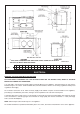
OVEN VENT PIPE CONNECTION OPTIONS Fig.
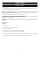
OVEN VENTING SYSTEMS See Figs. 4, 5 & 6 Pre-site visiting will have determined where and how the layout of the oven vent pipework should be designed and installed. It is then necessary to check that the pipework design and the pipework resistance are within the parameters possible. The appliance oven venting pipe can be achieved, up to a maximum length of 6 metres, through an outside wall or unused flue etc. Great care must be taken in all-timber houses.
Fig. 4 Fig. 5 DESN 513937 Fig.
USERS GUIDE HEALTH & SAFETY Consumer Protection As responsible manufacturers we take care to make sure that our products are designed and constructed to meet the required safety standards when properly installed and used.
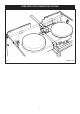
THE AGA COOKER Fig. 7 DESN 513946 The appliance is a heat storage cooker with a 13 amp element which will keep the temperature of the cooker constant when not in use and return it to constant temperature after use. The AGA is also supplied with the following accessories: 1 Large roasting tin with grill rack 1 Half size roasting tin with grill rack 2 Oven grid shelves A full description of the cooking with the AGA is given in the AGA book.
OPERATING THE AGA After the AGA has been Installed When first switched on, the AGA will emit an odour for a short while. This is simply due to protective oil burning off the hotplates. Wipe the inside of the lids whilst the AGA is heating up to avoid a film of this oil being deposited on the inside of the lids. Also, condensation may occur on the top and front plate. This should be wiped away as soon as possible.
THE HEAT INDICATOR Fig. 9 DESN 515920 The heat indicator above the Roasting oven door is a guide to the stored heat within the AGA, and does not directly relate to the Roasting oven centre oven temperature. It has 3 sections black, silver and red. To obtain your preferred working temperature the control knob can be adjusted slightly. Once set it is not recommended to adjust on a regular basis. An AGA is designed to work at an optimum setting.
GUIDE TO AGA COOKING As the Aga Cooker is heated differently from an ordinary cooker, exact conversions are not possible. Look in the Aga Book for a similar recipe. Below is a quick guide to oven usage.
FITTING OF OVEN SHELVES When using the oven shelves for the first time follow Figs. 10 - 13. Fig. 10 Fig. 11 DESN 512403 DESN 512404 REMOVAL OF OVEN SHELVES Fig. 12 Fig.
CARING AND CLEANING FOR THE AGA REMEMBER: BE CAREFUL OF THE HOT APPLIANCE. DO NOT A STEAM CLEANER TO CLEAN THIS COOKER. DO NOT USE ABRASIVE PADS OR OVEN CLEANER AGA Enamel Cleaner and AGA Chrome and Stainless Steel Cleaner are recommended. Top Plate and Front Plate The easiest way to clean the AGA top plate and front plate is to mop up spills as they happen.
For further advice or information contact your local AGA Specialist With AGA Rangemaster’s policy of continuous product improvement, the Company reserves the right to change specifications and make modifications to the appliance described and illustrated at any time. Manufactured by AGA Rangemaster Station Road Ketley Telford Shropshire TF1 5AQ England www.agaliving.com www.agacookshop.co.