
User guide


OVEN VENTING SYSTEMS
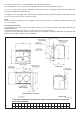
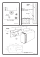
See Figs. 4, 5 & 6
Pre-site visiting will have determined where and how the layout of the oven vent pipework should be designed and
installed. It is then necessary to check that the pipework design and the pipework resistance are within the parameters
possible.
The appliance oven venting pipe can be achieved, up to a maximum length of 6 metres, through an outside wall or unused
flue etc. Great care must be taken in all-timber houses.
If the oven vent pipe passes through combustible material, there must be an airgap of at least 25mm around the pipe and
preferably wrapped with insulation material.
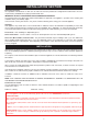
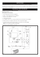
Setting the Vent Fan (Motor Speed)
Setting of the motor speed is carried out by adjusting the Voltage Regulator (VRI) on the controller PCB in conjunction with
a voltmeter. (See Fig. 4).
The max supply to the motor, should be limited to 20v (DC), for ideal operating condition.
Calculating the voltage for the particular pipework layout, is as follows:
1. Keep the pipe run as simple as possible - avoid bends.
2. Vertical risers are not permitted.
3. Pipe run should be horizontal - slight downwards slope towards fan.
Minimum 12 volts for first metre of vent pipe run inclusive of 1 bend.
Each extra metre add 1 volt.
Each extra bend add 2 volts.
Maximum allowed 20 volts.
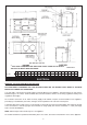
Alternative Oven Venting Systems
Venting may be achieved directly into the flue providing a stabiliser is fitted. See Fig. 5.
NOTE: IN THE OVEN VENTING INSTALLATION, WHETHER FAN ASSISTED OR NATURAL FLUE, PROVISION MUST
BE MADE FOR EASY ‘RIFLING’ OF THE PIPE WORK TO FACILITATE CLEANING.
8