
Specifications


13
In this application the mixer is part
of the noise figure measurement
system. The diagram below shows
the DUT and the mixer as the down
converter. The DUT in this case is an
amplifier. When using a mixer as part
of the measurement system, calibra-
tion is performed with the mixer in
the path. As in the illustration above,
70 MHz is used as the IF and a band
pass filter is added to the IF out of
the mixer. Choose the LO frequency
to be 70 MHz above the desired RF
and then calibrate and then insert
the device under test. In this case,
the device is tested at one frequency.
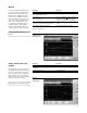
In this measurement, there is no
input filter to limit the noise input
to the upper sideband even though
the LSB was selected. The noise
from the upper sideband and lower
sideband will give a noise figure
higher than expected (3 dB).
Figure 14.
Setup using a
mixer as part
of the system
Instructions Keystrokes
Setup for the calibration process. Connect the noise source to the R port of
the mixer, the signal source to the L port
and the 70 MHz BPF to the I port. Connect
the other end of the 70 MHz BPF to the input
of the SA.
Analyzer setup - this assumes that the ENR [Mode Setup] {DUT Setup} {Amplifier}
factors are loaded in the PSA (Figure 14). Using the tab keys under the display, highlight
system downconverter and press {On}, move to
“LO” and enter [1] {GHz}. Move to “Sideband”
and select {LBS}. Move to “Frequency
Representation” and select “RF DUT Input”.
Set up the SA frequency. [Frequency] {Freq Mode} {Fixed}
{Fixed Freq 930 MHz}. Set the source to 1 GHz
and +7 dBm. [RF On]
Start the calibration process. [Meas Setup] {Calibrate} {Calibrate}
Place the DUT in the system between the No key presses required; the noise figure and
noise source and the RF port. gain is indicated in the box below the display.
Perform measurements with a mixer as
part of the system.
Measurements using a mixer
as part of the system