
Manual
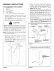
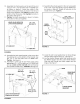

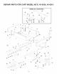

10.Assemblethefront panelovertheend of thecart
usingsix 1/4"x 1/2"hexboltsand1/4"SEMSnuts
as shown in figure 4. Leave two holes in the
bottomof thepanelemptyasshown.Pullthecart
bodyhalvestogetherandtighten the boltsin the
bottomofthefrontpanel,thentighten theboltsin
thesides.Seefigure4.
11.Tighten the boltsassembledin step 4 to fasten
the bottomof the carttogether.
LEAVE HOLES OPEN FOR
LATCH STAND BRACKET
1/4" x 1/2"
HEX BOLTS
1/4" SEMS NUT
x
&`
/
1/4" SEMS NUT
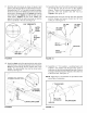
14. Assemble the wheel support to the cart using eight
5/16" x 3/4" truss head bolts and 5/16" SEMS nuts
as shown in figure 6. Heads of bolts go on the
inside of the cart. Tighten.
5/16" x 3/4"
TRUSS HEAD BOLT
WHEEL
SUPPORT
\
5/16"
SEMS
NUT
FIGURE 6
FIGURE 4
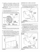
12. Assemble the latch stand bracket to the cart so that
the aligning tab is at the bottom of the bracket. Use
four 1/4" x 1/2" hex bolts and 1/4" SEMS nuts.
Tighten. See figure 5.
13. Assemble a corner cap to each front corner using
one ortwo 1/4" x 1/2" hex bolts and 1/4" SEMS nuts
per cap. Leave out the rear bolt if the cart has top
rails (model 45-0350 only). TIGHTEN. See figure 5.
LATCH STAND BRACKET _ --\
(Aligning tab at bottom)
Leaveout on
Model 45-0350
/\, i! ]
FIGURE 5
15. Lower the cart to rest upside down on its top flange
with the wheel support facing up. See figure 7.
16. Lay the drawbar tongue (open side facing up) onto
the Wheel Support and the Latch Stand Bracket.
Slide the axle through the wheel support and the
tongue. See figure 7.
AXLE
DRAW BAR
TONGUE
_,i LATCH STAND
',i BRACKET
FIGURE 7