
Manual
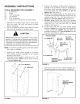
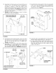


17. Hold the latch lock lever as shown in figure 8 and
place it down through the slot in the draw bar tongue.
Assemble the 5/16" x 4" hex bolt through the tongue,
the lever and two 5/16" SEMS nuts (one on each side
of the lever). Assemble the 5/1 6" nylock nut onto the
end of the bolt and tighten so that the bolt can still
rotate freely. Tighten the two 5/16" SEMS nuts
against the sides of the latch lock lever so that the
lever is centered in the slot. See figure 8.
5/16" SEMS NUTS
LATCH
_, LOCK
LEVER
5/16"
NYLOCK
_- NUT
FIGURE 8
19.
20.
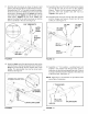
Assemble the end of the hitch bracket (two holes)
up through the slot at the front of the drawbar
tongue. Fasten it to the tongue using the 3/8"x1"
hex bolt, 3/8" lock washer and 3/8" hex nut.
Tighten. See figure 10.
Assemble the hitch pin through the hitch bracket
and the tongue and secure it with the 1/8" hair
cotter pin. See figure 10.
318"HEX
NUT
.................... 318" LOCK \
..........WASHER \
1/8" HAIR
COTTER
PIN
/
I
318" x 1"
HEX BOLT
=
HITCH
BRACKET
=-
HITCH PIN
/
FIGURE 10
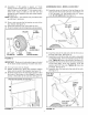
18. Hook the short end of the spring into the hole in the
latch lock lever. Use the spring puller tool to hook the
long end of the spring into the square hole in the
tongue. The spring puller tool can be stored when
finished. See figure 9.
,/
!----SPRING PULLER TOOL
LONG END
OF SPRING
LATCH LOCK LEVER
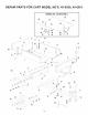
21. Assemble a 1" thin washer, a walking beam and
another 1" thin washer onto the pivot axle. Insert a
cotter pin into the axle and spread the ends. Press a
hub cap onto the flat washer. Repeat on the other end
of the pivot axle. See figure 11.
NOTE: Eight extra 1" flat washers are provided to take
up end play if necessary.
1" THIN WASHER
1/8" x 1-1/2"
\ COTTER PIN
HUB CAP
WALKING BEAM
FIGURE 9 FIGURE 11
6