45-0567 MOW-N-VAC IMPORTANT: The engine is shipped without oil. Add oil before starting the engine. the fastest way to purchase parts www.speedepart.com FORM NO.
TABLE OF CONTENTS SAFETY............................................................................ 3 ACCESSORIES AND ATTACHMENTS............................ 6 FULL SIZE HARDWARE CHART (CART)........................ 7 FULL SIZE HARDWARE CHART (ADAPTER)................. 7 CARTON CONTENTS...................................................... 8 ASSEMBLY..................................................................... 10 OPERATION...................................................................
SAFETY Any power equipment can cause injury if operated improperly or if the user does not understand how to operate the equipment. Exercise caution at all times when using power equipment. • • • • • • • • • • • • • • • Read and follow all instructions in this manual before attempting to assemble or operate this equipment. Failure to comply with these instructions may result in serious injury or death. Keep this manual in a safe place for future reference and for ordering replacement parts.
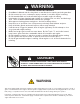
WARNING TO AVOID SERIOUS INJURY • • • • • • • • • • • • Read Owner’s Manual and all safety labels on machine before starting and using machine. Do Not remove top cover or attempt to empty contents of cart while engine is running. Do Not stand behind cart in exhaust discharge area while engine is running. Keep hands, feet, face, long hair and clothing out of chipper inlet, vac inlet, and discharge area. There are ROTATING BLADES inside these openings. Wear approved safety glasses and gloves.
SAFETY LABELS 46991 M117554 5
ACCESSORIES AND ATTACHMENTS The Remote Hose Kit, Model 45-0253, provides 12' x 5" diameter hose to clean around shrubs, patios, window wells and other areas not accessible to the tractor.
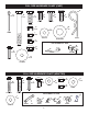
FULL SIZE HARDWARE CHART (CART) G A x2 B x5 E x4 D x4 C x2 43012 F x8 43182 47630 43001 H x8 23727 43010 M x4 L x4 I x12 47189 1543-69 J x9 47810 NOT SHOWN FULL SIZE 43574 K x9 P x8 43343 R19212016 O x2 N HA21362 23353 25910 Q x8 43661 736-0231 FULL SIZE HARDWARE CHART (ADAPTER) B x2 A x3 E x9 D x2 C x4 F x3 47810 G x5 43088 43080 H x12 47189 43081 43661 1509-90 43840 NOT SHOWN FULL SIZE O N I x5 L x2 K 44850 J x2 44489 23826 1543-69 8 M 42749 23825 23827
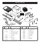
CARTON CONTENTS 3 2 1 4 9 10 5 7 8 6 11 16 12 13 14 15 17 21 18 22 20 19 23 REF. NO. PART NO. QTY. DESCRIPTION REF. NO. PART NO.
ASSEMBLY NOTE: This unit is shipped WITHOUT GASOLINE or OIL. After assembly, see separate engine manual for proper fuel and engine oil recommendations. • Assemble the rear tongue (6) to the wheel support by sliding the axle (21) through the holes in the tongue and wheel support as shown in figure 2.
• Assemble an axle clip (O), a wheel (9) and a 5/8" washer (M) onto each end of the axle. Assemble a second 5/8" washer onto each end of the axle if space allows. Secure both wheels in place using two cotter pins (A) and bending the ends. See figure 3. • Place the cart bed braces (20) and the cart tray onto the wheel support. Secure latch stand bracket underneath the tongue's latch lock lever. See figure 5.
• Attach the transition snout (18) to the top of the engine housing using four 5/16" x 3/4" hex bolts (E) and nylon washers (L). Attach the short hose (7) to the transition snout using a hose clamp (8) See figure 7. Note: Engine not shown for clarity. • Place a hose clamp (8) onto the end of the hose (11). Push the hose onto the hose adapter (nozzle). Tighten the hose clamp onto the hose and hose adapter. Do not collapse the hose adapter when tightening the clamp. See figure 9.
CART COVER ASSEMBLY • • Insert four 1/4" x 1" bolts (P) upwards through the holes in the side of the cart bed. Slide on a washer (Q) and spacer (H) onto each bolt. Attach a side rail (14) with the opening towards the inside of the cart, small hole towards the front and larger hole towards the back and secure with a 1/4" nylock nut (I). Repeat for the other side. See figure 11. Slide the cover (2) over the side rails. Make sure the hole for the hose is facing the front of the cart.
ASSEMBLING THE DECK ADAPTER TO THE MOWER DECK • NOTE: Make sure adapter clears gauge wheels on mower deck NOTE: Not all of the parts in the deck adapter hardware package will be needed for your particular fit up. • Position the adapter (19) over the deck opening, and check for fit of cutout as shown in figure 16. Trim cutout, if necessary, to allow tilting of adapter, keeping the fit as close as possible for best vacuum suction. Remove the mower discharge deflector from your mower deck.
• Assemble the adapter bracket to the deck using two 5/16" x 1-1/4" hex bolts,(B) 5/16" flat washers (H) and 5/16" nylock nuts (F). See figure 18. NOTE: It may be necessary to use extra 5/16" flat washers to shim under the bracket next to the deck surface. Ten extra washers have been furnished as shims. See figure 18. • With deck adapter positioned correctly over the discharge opening, use the adapter bracket as a template and drill three 9/32" diameter holes in the top of the deck adapter.
OPERATION KNOW YOUR MOW-N-VAC Read this owner's manual and safety rules before operating your Mow-N-Vac. Compare the illustration below with your Mow-N-Vac to familiarize yourself with the various controls and their locations. LATCH LOCK LEVER ON/OFF SWITCH FUEL CHOKE CONTROL SHUT-OFF THROTTLE CONTROL Controls speed of engine. CHOKE CONTROL Adjust to allow cold starting. FUEL SHUT-OFF Shuts off fuel flow to engine. THROTTLE CONTROL ON-OFF SWITCH Turns off engine ignition.
HOW TO START YOUR MOW-N-VAC HOW TO USE YOUR MOW-N-VAC CAUTION: Vehicle braking and stability may be affected with the addition of an accessory or an attachment. Be aware of changing conditions on slopes. WARNING: Never start or run the engine without all covers being properly attached to the blower housing and cart. • • • • • • • Check oil and gas in Mow-N-Vac engine. Attach spark plug wire to spark plug. Move choke lever on engine to CHOKE position. (A warm engine may not require choking.
MAINTENANCE CUSTOMER RESPONSIBILITIES • Read and follow the maintenance schedule and the maintenance procedures listed in this section. MAINTENANCE SCHEDULE Fill in dates as you complete regular service. se e e n h u us aso orag c h t a e c s e s e e ea y for ter ver efor E Be Af B Service Dates Check for loose fasteners X Check cover X Check tire pressure X Check engine oil level X Lubricate X Clean X X Maintain engine per instructions below and in engine manual.
SERVICE AND ADJUSTMENTS REMOVING THE IMPELLER REMOVING THE IMPELLER WARNING: Always stop the engine and remove the spark plug wire before working on the engine or the impeller housing assembly. 3/8" x 2" HEX BOLTS REMOVE • • • • Remove the outer impeller housing assembly. Remove the bolt from the impeller hub. See figure 20. Screw three 3/8" x 2" full thread bolts (sold separately) into the three nuts welded to the impeller until they contact the housing behind the impeller. See figure 20.
TROUBLESHOOTING PROBLEM POSSIBLE CAUSE(S) Engine fails to start 1. Spark plug wire disconnected. 2. Fuel tank empty, or stale fuel. 3. Fuel shut-off valve closed (if so equipped). 4. Faulty spark plug. CORRECTIVE ACTION 1. Connect wire to spark plug. 2. Fill tank with clean, fresh fuel. 3. Open fuel shut-off valve. Loss of power; operation erratic. 1. Connect and tighten spark plug wire. 2. Move choke lever to OFF position. 3. Clean fuel line; fill tank with clean fresh gasoline. 4.
5 3 1 46991 15 7 4 19 20 9 10 7 25 18 16 17 13 25 19 18 11 6 22 2 21 12 26 20 14 8 23 22 23 23 24
REF. NO. 1 2 3 4 5 6 7 8 9 10 11 12 13 14 PART NO. 2-16 47707 43012 24386BL1 43182 24908 40880G 65442BL3 24527BL3 24497BL1 25742BL3 27264 BL1 25010BL1 HA20186 QTY. DESCRIPTION 1 1 4 1 8 1 2 1 1 1 1 1 1 1 Cart Tray Handle Grip Hex Bolt, 1/4-20 x 3/4" Latch Stand Plate Hex Bolt, 5/16-18 x 3/4" Axle Wheel Rear Tongue Wheel Support Latch Stand Bracket Front Tongue Hitch Bracket Latch Lock Lever Spring REF. NO. 15 16 17 18 19 20 21 22 23 24 25 26 23 PART NO.
15 6 16 22 3-18 31 29 23 26 14 22 7 See page 24 11 2 3 M117554 17 M117554 38 24 30 9 13 12 10 8 39 19 39 ADAPTER #62468 1 20 13 8 36 26 21 25 10 25 28 4 25 13 26 25 24 34 8 27 33 27 5 10 32 27 26 13 25 26 8 13 35 13 18 34 37 26 25 10
REPAIR PARTS FOR MODEL 45-0567 REF. NO. PART NO. QTY. DESCRIPTION 1 45900BL3 2 2 45901BL3 3 REF. NO. PART NO. QTY. DESCRIPTION SIDE RAIL 22 43793 3 Hose Clamp 2 TUBES, SUPPORT 23 43790 1 Tarp Strap, 25" 43086 3 Lock Washer, 5/16" 24 43574 5 Hex Bolt, 3/8-16 x 3" 4 27304BL1 1 Bracket, Attachment 25 43088 11 Washer, 1/4" Std. 5 43840 2 Hex Bolt, 5/16-18 x 1-1/4" 26 1543-69 9 Nylon Washer 6 45902 1 Cart Cover 27 43081 10 Washer, 5/16" Std.
REPAIR PARTS LIST FOR 45-0567 17 2 8 2 12 92 5 4 52 8 10 3 24 11 68 4 16 1 14 9 13 7 4 15 9 REF. NO. PART NO. 10 24958BL1 1 Hose Hanger Bracket Housing Assembly, Inner 11 46584 3 Hex Nut, Whizlock 5/16-18 Housing Assembly, Outer 12 43081 4 Washer, 5/16" Std.
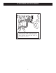
SUGGESTED GUIDE FOR SIGHTING SLOPES FOR SAFE OPERATION OF TRACTOR WITH ATTACHMENT FOLD ALONG DOTTE THIS IS D LINE A 10 D EGREE SLOPE ONLY RIDE UP AND DOWN HILL, NOT ACROSS HILL 10 DEGREES MAX. WARNING: To avoid serious injury, operate your tractor up and down the face of slopes, never across the face. Do not operate on slopes greater than 10 degrees. Make turns gradually to prevent tipping or loss of control. Exercise extreme caution when changing direction on slopes.
PARTS ORDERING/SERVICE the fastest way to purchase parts www.speedepart.com REPAIR PARTS Agri-Fab, Inc. 809 South Hamilton Sullivan, IL. 61951 217-728-8388 www.agri-fab.com © 2017 Agri-Fab, Inc. PRINTED IN U.S.A.