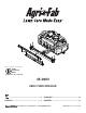
Want more information or assembly tips? Video Instruction Guide youtube.com/c/agrifab 45-0603 Zero Turn Sprayer ....................................................................3 FRANÇAIS........................................................ 12 ENGLISH.............................................................5 ESPAÑOL......................................................... 17 the fastest way to purchase parts www.speedepart.com FORM NO.
SAFETY RULES Remember, any equipment can cause injury if operated improperly or if the user does not understand how to operate the equipment. Exercise caution at all times when using this equipment. CAUTION: VEHICLE BRAKING AND STABILITY MAY BE AFFECTED WITH THE ADDITION OF AN ACCESSORY OR AN ATTACHMENT. BE AWARE OF CHANGING CONDITIONS ON SLOPES. LOOK FOR THIS SYMBOL TO POINT OUT IMPORTANT SAFETY PRECAUTIONS. IT MEANS - ATTENTION! BECOME ALERT! YOUR SAFETY IS INVOLVED.
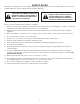
CARTON CONTENTS - PARTS 1 2 4 6 3 5 9 11 10 7 8 13 12 REF QTY 1 2 3 4 5 6 7 1 1 1 1 2 2 2 PART NO 6-926PH 2-541BL3 2-465 ST43673 45908BL3 45909 45814BL3 DESCRIPTION REF QTY Boom Assembly ZT Bracket, Boom Support 15 Gallon Tank, Drilled Spray Wand With Brass Tip Mounting Bracket U-Bolt, 7.0 X 3.
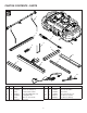
CARTON CONTENTS - HARDWARE NOT SHOWN FULL SIZE A B C x4 x1 D x2 x3 E F 43351 43084 43432 46071 43015 G x3 x4 47189 H x1 41657 I x2 HA21362 x4 44072 O x1 J K x4 L x2 43003 1540-118 M x4 N x4 43081 x1 28325 43343 HA23636 REF QTY A B C D E F G H 1 4 2 3 4 3 1 2 PART NO 43351 43084 43432 46071 43015 47189 41657 HA21362 DESCRIPTION REF QTY Bolt, Hex 1/2-13 X 1-1/4 GR5 Bolt, Hex 5/16-18 X 1-3/4 GR5 Bolt, Hex 3/8-16 X 2-1/2 GR5 Bolt, Hex 1/4-20 X 3-1/4 GR5 Nut, Hex
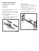
ASSEMBLY INSTRUCTIONS STEP 2: (SEE FIGURE 2) TOOLS REQUIRED FOR ASSEMBLY (1) Adjustable Wrench (2) 7/16" Wrenches (2) 1/2" Wrenches (2) 9/16" Wrenches Lay out and identify the parts and hardware using the illustrations on page 3 and page 4. ASSEMBLE THE HITCH MOUNT ASSEMBLY • Attach the hitch mount assembly (8) to the tractor frame using two U-bolts (6) secured with two mounting brackets (5), four washers (J), and four Nylock hex nuts (E). Do not tighten.
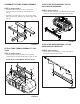
ASSEMBLE THE TUBE FRAME ASSEMBLY ATTACH THE TANK ASSEMBLY TO THE HITCH MOUNT ASSEMBLY STEP 3: (SEE FIGURE 3) • • Attach the tube frame (10) to the receiver hitch frame (9) using a hex bolt (D) and a Nylock hex nut (F). STEP 5: (SEE FIGURE 5) • Attach the tank assembly to the hitch mount assembly using one clevis pin (N) and one hair cotter pin (O). Attach the rear tube frame (11) to the receiver hitch frame (9) using two hex bolts (D) and two Nylock hex nuts (F).
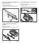
ATTACH THE BOOM SUPPORT BRACKET TO THE TRACTOR HITCH ATTACH WIRE HARNESS TO THE BATTERY STEP 7: (SEE FIGURE 7) • Connect the wire harness switch (12) to the wire harness battery (13). • Attach the wire harness switch (12) to pump harness. • STEP 9: (SEE FIGURE 8) Attach the boom support bracket to the tractor hitch using one hex bolt (A), two washers (K), and one hex nut (G).
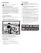
OPERATION USING THE SPRAYER CAUTION: Wear eye and hand protection and protective clothing when handling and working with lawn chemicals. CAUTION: Connect to a 12 V battery only. 1. PUMP PRESSURE SWITCH The pump pressure switch turns off the pump when it reaches its maximum pressure setting. Very low flow demand may cause the switch to rapidly cycle the pump on and off. Rapid on and off cycling must be limited to no more than 6 times per minute.
MAINTENANCE USING THE SPRAY GUN 1. Shut off the boom by turning the boom valve to "OFF". AFTER EACH USE SPRAYER RECIRCULATION 1. 1. The sprayer is equipped with a recirculation valve to aid in material agitation and pressure control. 2. This valve is in the “open” position when the valve handle is in line with the hose (pictured), “closed” when perpendicular to the hose. Fill the sprayer part way with water and pump the water out through the boom assembly and the handgun.
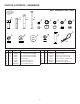
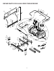
REPAIR PARTS FOR 45-0603 Zero Turn Sprayer 42 32 45 29 11 43 29 46 44 11 47 48 32 49 34 6 2 5 9 11 16 6 9 8 11 25 11 15 11 12 6 12 11 33 31 29 30 11 11 50 11 44 10 11 28 26 54 24 11 13 14 53 59 1 4 35 58 17 51 18 39 36 3 40 56 1 4 20 37 23 7 60 55 7 19 41 38 55 57 10 52 61 22 21
REPAIR PARTS FOR 45-0603 Zero Turn Sprayer REF QTY PART NO 1 2 46677 2 4 ST65001 3 4 43084 4 3 46071 5 1 43351 6 8 44072 7 3 47189 8 1 41657 9 2 1540-118 10 1 ST43655 11 12 ST43010 12 2 ST43014 13 1 ST43182 14 1 ST43258 15 1 ST43183 16 1 ST43235 17 1 ST43287 18 4 28325 19 1 HA23636 20 1 43343 21 1 2-684 22 1 2-685 23 1 ST43191 24 1 2-465 25 1 ST43918 26 1 ST43175 27 1 ST44017 28 1 2-342 29 2 2-319 30 1 2-318 31 1 2-337 32 2 2-314 DESCRIPTION Screw, 10-24 X 3/8 PL Screw, 10-24 X 1" Truss Head Bolt, Hex 5/16
RÈGLES DE SÉCURITÉ N’oubliez pas que tout équipement peut causer des blessures s’il est utilisé de manière incorrecte ou si l’utilisateur ne comprend pas comment l’utiliser. Faites preuve de prudence à tout moment lorsque vous utilisez cet équipement. RECHERCHEZ CE SYMBOLE POUR SIGNALER D’IMPORTANTES PRÉCAUTIONS DE SÉCURITÉ. IL SIGNIFIE - FAITES ATTENTION! SOYEZ ALERTE! VOTRE SÉCURITÉ EST EN JEU.
INSTRUCTIONS D’ASSEMBLAGE OUTILS REQUIS POUR L’ASSEMBLAGE Remarque : ne serrez pas trop les boulons hexagonaux (1) Clé réglable (2) Clés 7/16 po (2) Clés 1/2 po (2) Clés 9/16 po FIXER L’ASSEMBLAGE DU RÉSERVOIR À L’ASSEMBLAGE DU MONTAGE D’ATTELAGE Disposez et identifiez les pièces et le matériel à l'aide des illustrations à la page 3 et la page 4.
FONCTIONNEMENT UTILISATION DU PULVÉRISATEUR ATTENTION : Portez des protections pour les yeux et les mains et portez des vêtements de protection lors de la manipulation et de l’application de produits chimiques sur les pelouses. ATTENTION : Connectez seulement à une batterie de 12 V. COMMUTATEUR DE PRESSION DE POMPE 1. La pression de la pompe se met à l’arrêt lorsqu’elle atteint le réglage de pression maximal.
ENTRETIEN UTILISATION DU PISTOLET DE PULVÉRISATION 1. Éteindre la rampe en tournant la soupape de la rampe à « OFF ». APRÈS CHAQUE UTILISATION RECIRCULATION DU PULVÉRISATEUR 1. 1. Ce pulvérisateur est muni d’une soupape de recirculation qui permet d’agiter le matériau et contrôler la pression. Remplissez le réservoir à moitié avec de l’eau et pompez l’eau dans l’assemblage de la rampe et le pistolet. Utilisez le pistolet pour nettoyer l’intérieur du réservoir. 2.
PIÈCES DÉTACHÉES POUR 45-0603 PULVÉRISATEUR ZT RÉF. QTÉ 1 2 3 2 4 4 N° DE PIÈCE 46677 ST65001 43084 4 5 3 1 46071 43351 6 7 8 9 10 11 12 13 8 3 1 2 1 12 2 1 44072 47189 41657 1540-118 ST43655 ST43010 ST43014 ST43182 14 15 1 1 ST43258 ST43183 16 1 ST43235 17 1 ST43287 18 4 28325 19 20 21 1 1 1 HA23636 43343 2-684 22 1 2-685 23 24 25 26 1 1 1 1 ST43191 2-465 ST43918 ST43175 27 1 ST44017 28 29 30 31 32 1 2 1 1 2 2-342 2-319 2-318 2-337 2-314 DESCRIPTION RÉF.
NORMAS DE SEGURIDAD Recuerde que cualquier equipo puede causar lesiones si se utiliza incorrectamente, o si el usuario no sabe utilizarlo. Tenga cuidado en todo momento al usar este equipo. BUSQUE ESTE SÍMBOLO PARA IDENTIFICAR PRECAUCIONES DE SEGURIDAD IMPORTANTES. SIGNIFICA: ¡ATENCIÓN! ¡ESTÉ ALERTA! SU SEGURIDAD ESTÁ EN JUEGO. ATENCIÓN: ACOPLAR UN ACCESORIO O COMPLEMENTO A UN VEHÍCULO PUEDE AFECTAR SU CAPACIDAD DE FRENADO Y ESTABILIDAD. ESTÉ ATENTO A LOS CAMBIOS DE CONDICIONES EN LAS PENDIENTES.
INSTRUCCIONES PARA EL ARMADO HERRAMIENTAS NECESARIAS PARA EL ARMADO Nota: No apriete demasiado los pernos hexagonales (1) Llave ajustable (2) Llaves de 7/16" (2) Llaves de 1/2" (2) Llaves de 9/16" FIJAR EL MONTAJE DEL TANQUE AL MONTAJE DE ENGANCHE PASO 5: (VER FIGURA 5) Despliegue las piezas y los herrajes e identifíquelos guiándose por las ilustraciones en las páginas 3 y 4. • Fije el montaje del tanque al montaje del enganche armado con un pasador de chaveta (N) y un pasador de horquilla (O).
FUNCIONAMIENTO USAR EL PULVERIZADOR ATENCIÓN: Use protección para los ojos y las manos y lleve ropa protectora cuando manipule y trabaje con productos químicos para el césped. ATENCIÓN: Conectar solo a una batería de 12 V. 1. INTERRUPTOR DE PRESIÓN DE LA BOMBA La bomba de presión apaga la bomba, cuando esta alcanza su ajuste máximo de presión. Una demanda de flujo muy baja podría provocar que el interruptor fuerce a la bomba a hacer ciclos rápidos de encendido y apagado.
MANTENIMIENTO USAR LA PISTOLA PULVERIZADORA 1. Apague el brazo girando su válvula a la posición "OFF" (CIERRE). DESPUÉS DE CADA USO RECIRCULACIÓN DEL PULVERIZADOR 1. 1. El pulverizador está equipado con una válvula de recirculación para ayudar con la agitación del material y el control de la presión. Llene una parte del tanque con agua y bombéela por el montaje del brazo y la pistola. Use la pistola para lavar el interior del tanque. 2.
PIEZAS DE REPUESTO PARA EL PULVERIZADOR GIRO CERO 45-0603 REF. CANT. PIEZA N.° 1 2 46677 2 4 ST65001 3 4 43084 4 5 3 1 46071 43351 6 8 44072 7 8 9 10 11 12 13 3 1 2 1 12 2 1 47189 41657 1540-118 ST43655 ST43010 ST43014 ST43182 14 15 16 1 1 1 ST43258 ST43183 ST43235 17 1 ST43287 18 4 28325 19 20 21 1 1 1 HA23636 43343 2-684 22 1 2-685 23 24 25 26 27 1 1 1 1 1 ST43191 2-465 ST43918 ST43175 ST44017 28 29 30 31 32 1 2 1 1 2 2-342 2-319 2-318 2-337 2-314 DESCRIPCIÓN REF. CANT.
THIS PAGE INTENTIONALLY LEFT BLANK 22
THIS PAGE INTENTIONALLY LEFT BLANK 23
the fastest way to purchase parts www.speedepart.com REPAIR PARTS Agri-Fab, Inc. 809 South Hamilton Sullivan, IL. 61951 217-728-8388 www.agri-fab.com This document (or manual) is protected under the U.S. Copyright Laws and the copyright laws of foreign countries, pursuant to the Universal Copyright Convention and the Berne convention.