™ owner's manual MANUAL DE USUARIO NOTICE D’UTILISATION Model No. Modelo No. Modèle no LBD48D 48" SNOW BLADE CUCHILLA QUITANIEVE DE 48" (122 CM) CAUTION: Read Rules for Safe Operation and Instructions Carefully PRECAUCIÓN: Lea Cuidadosamente las Reglas e Instrucciones de Seguridad ATTENTION: Lire et suivre attentivement les instructions et consignes de sécurité de cette notice. LAME CHASSE-NEIGE DE 48 PO.
ENGLISH TABLE OF CONTENTS SAFETY RULES.............................................................. 2 CARTON CONTENTS..................................................... 2 FULL SIZE HARDWARE CHART.................................... 3 ASSEMBLY...................................................................... 4 OPERATION...................................................................11 MAINTENANCE............................................................ 12 SERVICE AND ADJUSTMENTS................
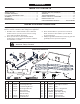
ENGLISH SHOWN FULL SIZE G A H C B K N I O L J M W D F E Q X P V S R U T NOT SHOWN FULL SIZE Y Z BB AA CC DD HARDWARE PACKAGE ref qty part no.
ENGLISH ASSEMBLY SKIP TO STEP 3 IF YOUR TRACTOR HAS TWO FRONT BRACKETS FOR ATTACHING THE MOWER DECK.
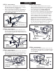
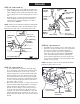
STEP 2: (SEE FIGURE 2) • • USE THESE INSTRUCTIONS FOR ALL TRACTORS Measure the distances L, H and W. L = distance from center of lower holes in frame bracket to front of tractor frame. H = distance to center of hole in frame bracket that is closest to being 6" above ground level. W = distance between the inside of the frame brackets. Proceed to step 4. STEP 4: (SEE FIGURE 4) Refer to page 6 for examples of how to attach the Hanger Brackets to some other tractor models.
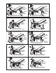
SEARS 917 SERIES & HUSQVARNA TRACTORS WITH CENTER DECK SUSPENSION BRACKET AND 16" TIRES SEARS 917 SERIES & HUSQVARNA TRACTORS WITH CENTER DECK SUSPENSION BRACKET AND 15" TIRES 3/8" x 1" CARRIAGE BOLT 3/8" x 1" CARRIAGE BOLT 12.75" 1/2" WASHER (LARGE) 12.
JOHN DEERE D100 SERIES TRACTORS JOHN DEERE LT 13" 13" 5/16" x 1" HEX BOLT 5/16" x 1" HEX BOLT FRAME BRACKET FRAME BRACKET LOCATE HANGER BRACKETS IN FRONT SET OF SLOTS IN THRUST CHANNEL LOCATE HANGER BRACKETS IN FRONT SET OF SLOTS IN THRUST CHANNEL 7
ENGLISH STEP 5: (SEE FIGURE 5) • • STEP 8: (SEE FIGURE 8) Attach the Rear Locating Bracket to the top of the Rear Mounting Bracket using two 3/8" x 1" Carriage bolts and 3/8" nylock nuts. Tighten nuts. Attach the Rear Support Channels to the middle set of holes in the sides of the Rear Mounting Bracket using four 3/8" x 1" Carriage Bolts and 3/8" nylock nuts. Finger tighten only.
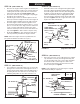
ENGLISH STEP 10: (SEE FIGURE 10) • • • • • STEP 12: (SEE FIGURE 12) Place the two angle lock bars together so that all holes are aligned. Assemble a 3/8" x 1-1/4" carriage bolt and a 3/8" nylock nut in the top hole. Be sure to insert the bolt from the side indicated. Finger tighten only. Insert the round hook end of the angle lock spring up through the hole in bracket (a). Hold the angle lock bars so that the square holes are at the top.
ENGLISH STEP 14: (SEE FIGURE 14) • • 1/8" x 1-1/4" COTTER PIN (O) Assemble ball end of control cable up through hole in cable end fitting and pull until ball slips inside curled edge of fitting as shown. If ball won't slip under edge of curl it will need to be inserted through open end of curl. Assemble a 1/4" x 1-1/4" hex bolt down through the cable end fitting, the 5/8" long spacer and the left hand hole in the channel assembly. Secure with a 1/4" nylock nut. Tighten.
ENGLISH STEP 17: (SEE FIGURE 17) • • STEP 19: (SEE FIGURE 19) From the left side, insert the welded end of the lift handle rod through the exposed holes in the end of the channel assembly. Next, insert the lift link pin through the hole in the bracket that is welded to the lift handle rod. (The lift link is pre-assembled to the pivot support bracket). Secure the bracket with a small hairpin cotter. Apply a light coating of oil to the straight upper portion of the lift handle rod.
OPERATION KNOW YOUR SNOW BLADE Read this owner's manual and safety rules before operating your snow blade. Compare the illustration below with your snow blade to familiarize yourself with the various controls and their locations. LOCK RELEASE GRIP ASSEMBLY LIFT HANDLE TUBE BLADE PIVOT ROD ANGLE LOCK BARS BLADE ADJUST SPRING LIFT HANDLE ROD BLADE SHOE CONTROL CABLE BLADE PIVOT SHAFT LOCK RELEASE GRIP ASS'Y.
Wheel weights and tire chains must be used with your snow blade for traction. These accessories are available at your nearest Sears retail store. CAUTION: Inspect carefully the area to be worked before operating the snow blade. Avoid pipes, roots, curbs or other heavy obstructions. Using the Snow Blade • Prepare the lawn tractor engine for cold weather using instructions furnished with the lawn tractor. • Always begin with the transmission in first (low) gear and gradually increase speed as required.
SERVICE AND ADJUSTMENTS To Adjust Blade Spring • To Adjust the Blade Pivot Lock Mechanism The tension of the blade adjust spring may be altered to permit the blade to tilt forward to bypass solid obstructions. To change the spring tension, adjust the nuts at upper end of the spring bolt. Turn the nuts counterclockwise to relieve tension and clockwise to increase tension. Refer to figure 15 on page 10.
ESPAÑOL ÍNDICE REGLAS DE SEGURIDAD...................................................... 14 CONTENIDO DEL CARTÓN................................................... 14 CUADRO DE FERRETERÍA -TAMAÑO REAL........................ 15 ARMADO............................................................................ 16-19 OPERACIÓN...................................................................... 19-20 MANTENIMIENTO.................................................................. 20 SERVICIO Y AJUSTES.......
ESPAÑOL PIEZAS MOSTRADAS A TAMAÑO REAL G A H C B K N I O L J M W D F E Q X P V S R U T NO SE MUESTRA A TAMAÑO REAL Y Z BB AA CC DD PAQUETE DE FERRETERIA ref. cant. partE no A 1 46071 B 1 1509-90 C 4 43063 D 1 43085 E 4 710-0305 F 18 43350 G 3 47189 H 5 47810 I 24 HA21362 J 2 712-0256 K 1 HA3980 L 2 44062 M 3 43343 N 4 43055 O 2 43010 descripcion ref. cant.
ADAPTACIONES PARA DIVERSOS TRACTORES TRACTORES SEARS DE LA SERIE 917 CON MÉNSULA DE SUSPENSION CENTRAL (15" NEUMÁTICOS) TRACTORES SEARS DE LA SERIE 917 CON MÉNSULA DE SUSPENSION CENTRAL (16" NEUMÁTICOS) (F) PERNO DE CARRUAJE DE 3/8" x 1" 12.75" (32 cm) (F) PERNO DE CARRUAJE DE 3/8" x 1" 12.
ADAPTACIONES PARA DIVERSOS TRACTORES TRACTORES JOHN DEERE DE LA SERIE D100 TRACTORES JOHN DEERE LT 13" (33 CM) 13" (33 CM) (C) PERNO DE HEXAGONAL DE 5/16" x 1" (C) PERNO DE HEXAGONAL DE 5/16" x 1" MÉNSULA DE MARCO MÉNSULA DE MARCO COLOQUE LAS MÉNSULAS DE COLGAR EN EL JUEGO DE RANURAS DEL FRENTE EN LA VIGA DE CANAL DE EMPUJE COLOQUE LAS MÉNSULAS DE COLGAR EN EL JUEGO DE RANURAS DEL FRENTE EN LA VIGA DE CANAL DE EMPUJE 18
ESPAÑOL HERRAMIENTAS NECESARIAS PARA EL ARMADO (1) (1) (1) (1) (2) (2) USE ESTAS INSTRUCCIONES SI SU TRACTOR TIENE DOS MÉNSULAS DELANTERAS PARA ACOPLAR LA CORTADORA DE CÉSPED. alicates martillo llave ajustable (o juego de llaves de copa) llave de 9/16" de extremo abierto o de caja llaves de 7/16" de extremo abierto o de caja llaves de 1/2" de extremo abierto o de caja ATENCIÓN: Regrese al paso 1 si su tractor tiene sólo una ménsula delantera para acoplar la cortadora de césped.
ESPAÑOL PASO 6: (VEA LA FIGURA 6) • Deslice los canales de ménsula trasera debajo de la parte trasera del tractor. Acople la ménsula de montaje trasero a la barra de arrastre del tractor con un pasador de grillete de 5/8 pulg. x 1-3/4 pulg. y un pasador de horquilla grande. • En este punto apriete el Perno de carruaje de 3/8" y la tuerca de cierre de nilón colocados previamente en las barras de cierre de angulo.
ESPAÑOL PASO 15: (VEA LA FIGURA 15) • Para fijar la cuchilla en el conjunto de canal, alinee los huecos con muesca en la placa de giro con los huecos con muesca en la cuchilla. Inserte hacia abajo una chaveta de dos patas de 1/8" x 1-1/4" a través del hueco en la parte curva del eje de giro de la cuchilla. Abra los extremos de la chaveta. Desde el lado izquierdo, introduzca el eje de giro de la cuchilla por los huecos con muesca, con su extremo curvo mirando hacia arriba.
ESPAÑOL Para Girar la Cuchilla • Levante la cuchilla a posición de transporte. Para abrir el cierre de la cuchilla, presione contra el tubo de manejo la palanca de abertura de cierre. Para girar la cuchilla, mantenga la palanca deprimida y presione hacia el frente o tire hacia atrás el tubo de manejo, delizándolo a lo largo de la barra de levante. Suelte la palanca para fijar la cuchilla en posición de centro, mano derecha o mano izquierda. Vea la Figura 22.
ESPAÑOL SERVICIO Y AJUSTES MÉNSULA SOLDADA DE MONTAJE DE CABLE Ajuste del Resorte de la Cuchilla • La tensión del resorte de ajuste de la cuchilla puede cambiarse para permitir que la cuchilla se incline hacia delante para pasar sobre una obstrucción. Para cambiar la tensión del resorte, ajuste las tuercas en el extremo superior del perno de resorte.
FRANÇAIS TABLE DES MATIÈRES CONSIGNES DE SÉCURITÉ................................................... 22 PIÈCES CONTENUES DANS LE CARTON............................. 22 PRÉSENTATION DU MATÉRIEL GRANDEUR NATURE......... 23 ASSEMBLAGE.................................................................... 24-27 UTILISATION........................................................................27-28 ENTRETIEN............................................................................. 28 RÉPARATIONS ET RÉGLAGES...
FRANÇAIS PIÈCES À L’ÉCHELLE G A B K H C N I O L J M W D F E Q X P V S R U T PIÈCES NON À L’ÉCHELLE Z Y BB AA DD CC SAC DE PIÈCES RÉF. QTÉ PIÈCE no. A 1 46071 B 1 1509-90 C 4 43063 D 1 43085 E 4 710-0305 F 18 43350 G 3 47189 H 5 47810 I 24 HA21362 J 2 712-0256 K 1 HA3980 L 2 44062 M 3 43343 N 4 43055 O 2 43010 DESCRIPTION RÉF. QTÉ Boulon hex., 1/4 po. x 3-1/4 po. Boulon hex., 1/4 po. x 1-1/4 po. Boulon hex., 5/16 po. x 1 po. Boulon hex., 5/16 po. x 1-1/2 po.
FIXATION SUR DIVERS TYPES DE TRACTEURS TRACTEURS SEARS DE LA SÉRIE 917 ET HUSQVARNA AVEC SUPPORT DE SUSPENSION CENTRAL 12.75 PO. (32 CM) TRACTEURS JOHN DEERE LT 13 PO. (22 CM) (F) BOULON DE CARROSSERIE, 3/8 PO. x 1 PO. (C) BOULON HEX 5/16 PO. x 1 PO. BOULON HEX 3/8 PO. x 1 PO.
FIXATION SUR DIVERS TYPES DE TRACTEURS TRACTEURS JOHN DEERE DE LA SÉRIE D 100 TRACTEURS JOHN DEERE LT 13 PO. (22 CM) 13 PO. (22 CM) (C) BOULON HEX 5/16 PO. x 1 PO. (C) BOULON HEX 5/16 PO. x 1 PO.
FRANÇAIS UTILISEZ CES INSTRUCTIONS SI VOTRE TRACTEUR EST ÉQUIPÉ DE DEUX SUPPORTS AVANT DE FIXATION DU PLATEAU DE COUPE. OUTILS NÉCESSAIRES POUR L’ASSEMBLAGE (1) (1) (1) (1) (2) (2) Pinces Marteau Clé à molette (ou clé à douilles) Clé à fourche de 9/16 po. ou clé polygonale Clé à fourche de 7/16 po. ou clé polygonale Clé à fourche de 1/2 po. ou clé polygonale ATTENTION : repassez à l’étape 1 si votre tracteur n’est doté que d'un seul support avant de fixation du plateau de coupe.
FRANÇAIS • ÉTAPE 6 : (VOIR LA FIGURE 6) • Faites glisser les barres de renforcement arrières sous la partie arrière du tracteur. Fixez le support de montage arrière à la barre d’attelage à l’aide de l’axe de chape de 5/8 po x 1-3/4 po et d’une grande goupille fendue. Serrez à présent le boulon de carrosserie de 3/8 po. et le contre-écriu en nylom que vous avez installez sur les leviers de verrouillage d’angle.
FRANÇAIS ÉTAPE 19 : (VOIR LA FIGURE 19) • Installez la poignée en plastique sur l’ensemble de la poignée de déblocage. • Fixez l’ensemble de la poignée de déblocage sur le manche d’élévation en utilisant un boulon hex. de 5/16 po. x 1-1/2 po. et un contre-écrou en nylon de 5/16 po. Ne pas trop serrer le contre-écrou en nylon. L’ensemble de la poignée doit pouvoir tourner librement.
FRANÇAIS Pour faire tourner ou basculer la lame • Relevez la lame à sa position de transport. Pour débloquer la lame, appuyez sur la poignée de déblocage contre le manche. Pour tourner la lame ou la faire basculer, continuez à serrer la poignée et poussez ou tirez sur le manche afin de le glisser le long du bras du manche d’élévation. Relâchez la poignée afin de bloquer la lame en position droite, gauche ou droit devant. Réferez-vous à l’illustration 22.
FRANÇAIS RÉPARATIONS ET RÉGLAGES SUPPORT DE CÂBLE SOUDÉ Pour régler la tension du ressort de la lame • Vous pouvez changer la tension du ressort de réglage de la lame pour que la lame puisse basculer vers l’avant afin d’éviter les obstacles. Pour modifier la tension du ressort, réglez les écrous situés à l’extrémité supérieure du boulon du ressort.
BLANK PAGE 33
40 43 18 32 34 51 53 39 24 41 38 58 60 6 47 41 52 54 25 51 27 25 D 52 23 52 36 C 31 50 52 49 16 46 41 B 30 38 55 42 37 25 17 41 51 52 51 47 C 26 47 45 33 48 35 15 36 25 A 16 A 52 B 11 57 12 10 52 67 56 13 48 8 34 52 51 51 14 19 36 3 8 35 63 9 D 20 7 28 52 51 29 59 1 48 6, 52 6, 52 6 52 59 44, 63 61 6 4 22 OPTIONAL ACCESSORY 55 63, 64 62 58 6 21 21 4 55 67 58 52 51 65,66 61 2 4 5 REPAIR PARTS LIST FO
REF. no. 1 2 3 4 5 6 7 8 9 10 11 12 13 14 15 16 17 18 19 20 21 22 23 24 25 26 27 28 29 30 31 32 33 34 PART no. 23955 23956 62980 43080 44326 47810 43081 24690 64732 24347 43262 23131 1540-118 23958 23130 24659 46066 25125 9466R 44071 43015 44074 49808 62561 43055 46053 63033 25121 25122 24023 48167 65519 23151 23856 1 1 1 6 4 15 4 2 1 1 1 1 1 1 1 2 1 1 1 1 2 1 1 1 4 2 1 1 1 1 1 1 2 1 QTY.
the fastest way to purchase parts www.speedepart.com © 2004 Agri-Fab, Inc. REPAIR PARTS Agri-Fab, Inc. 809 South Hamilton Sullivan, IL. 61951 217-728-8388 www.agri-fab.