
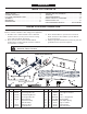
Product Manual


9
(Top View)FIGURE 11
FIGURE 12 (Right Hand Side View)
FIGURE 13 (Left Hand Side View)
(Right Hand Side View)FIGURE 10
ENGLISH
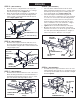
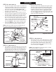
STEP 10: (SEE FIGURE 10)
• Placethetwoanglelockbarstogethersothatallholes
arealigned.Assemblea3/8"x1-1/4"carriageboltand
a3/8"nylocknutinthetophole.Besuretoinsertthe
boltfromthesideindicated. Finger tighten only.
• Inserttheroundhookendoftheanglelockspringup
throughtheholeinbracket(a).
• Holdtheanglelockbarssothatthesquareholesare
atthetop.Insertthestraighthookendoftheanglelock
springthroughthemiddleholeinbothanglelockbars.
• Inserttheanglelockbarsdownthroughtheslotin
thechannel.Underneaththechannel,placea1"long
spaceroneachsideoftheanglelockbarsandinsert
a1/4"x3-1/4"boltthroughthechannel,theangle
lockbarsandthespacers.Securetheboltwitha1/4"
nylocknut.Tightensothatlockbarscanpivotfreely.
• Atthistimetightenthe3/8"carriageboltandnylon
locknutpreviouslyassembledtoanglelockbars.
NOTE: Whentheanglelockbarsarepulledback,the
pivotplateshouldunlockandbefreetopivot.
STEP 11: (SEE FIGURE 11)
• Useahammertotapa3/8"palnutontooneendofthe
springmountrod.Inserttherodthroughtherearsetof
holesinthepivotplate.Supporttheassembledendof
thespringmountrodonablockofwood,andtapthe
remaining3/8"palnutontotheotherendoftherod.
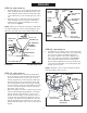
STEP 12: (SEE FIGURE 12)
• Assemblea3/8"x1-1/4"carriageboltthroughthesquare
holeinthecablemountbracketandthroughthesquare
holeintheanglelockbarsasshown.(Thecarriagebolts
shouldfaceinoppositedirections.)Usingpliersholdthe
cablemountbracketinposition,anglingdowntowards
theL.H.holeinthechannelasshown.Securewitha3/8"
nylocknut. Tighten.Referalsotogure14forthecorrect
angleforthecablemountbracket.
STEP 13: (SEE FIGURE 13)
• Selecttheendofthecontrolcablethathasnorubber
cap.Assembleone5/16"jamnutapproximately3/4"
ontothethreadedendofthecontrolcable.Assemble
thethreadedcableendthroughtheroundholein
thecablemountbracketasshownandsecurewith
another5/16"jamnut.Tighten.
NOTE: Someadjustmentofjamnutsmayberequired
afterbladeassemblyiscompleted.
1/4" x 3-1/4"
HEX BOLT (A)
1" SPACERS (U)
1/4" NYLOCK
NUT (G)
ANGLE
LOCK
SPRING (X)
(a)
3/8"x 1-1/4"
CARRIAGE BOLT (E)
CHANNEL
ANGLE
LOCK BARS
3/8" NYLOCK
NUT (I)
3/8" PALNUT (P)
PIVOT
PLATE
SPRING
MOUNT
ROD (Z)
3/8" PALNUT (P)
3/8" x 1-1/4"
CARRIAGE BOLT (E)
3/8" NYLOCK
NUT (I)
ALIGN CABLE
MOUNT BRACKET (W)
WITH L.H. HOLE
ANGLE
LOCK
BARS
FRONT
CHANNEL ASSEMBLY
5/16" JAM NUT (J)
5/16" JAM NUT (J)
CABLE MOUNT
BRACKET
REAR
3/4"