
Information

QPX600D - dual 600 watt dc power supply with
PowerFlex+
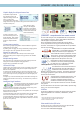
80V, 50A max.
5A0A 10A 15A 20A 25A 30A 35A 40A 45A 50A
0V
10V
20V
30V
40V
50V
60V
70V
80V
QPX600D
PowerFlex+
Power Envelope
(600W max.
per output)
Dual independent or tracking 600 watt outputs
Ultra-wide range of voltage/current combinations
Up to 80V and up to 50A within each power envelope
Isolated tracking of voltage only, or voltage and current
Smart metering and tracking functions facilitate
series or parallel wiring for up to 160V or 100A
Low output noise and ripple
High setting resolution of 1mV
Variable OVP and OCP trips
Analog control interfaces for voltage and current
GPIB, RS-232, USB and LAN (LXI) interfaces (QPX600DP)
The QPX600D is a dual output dc power supply with a maximum total output
power of 1200 watts and is suited to both bench-top and system applications.
The QPX600DP incorporates full digital remote control using USB, RS-232, LAN
and GPIB interfaces. Both models include analog remote control.
PowerFlex+
The QPX600D is a different type of laboratory power supply designed to meet
the need for flexibility in the choice of voltage and current.
A conventional PSU has a fixed current limit giving a power capability that
reduces directly with the output voltage.
The TTi PowerFlex+ design of the QPX600D enables higher currents to be
generated at lower voltages within an overall power limit envelope. Each
output can provide more than six times the current of a conventional PSU of
the same maximum voltage and power (see power curve).
PowerFlex+ uses a balanced multi-phase converter system to minimise ripple
and improve dynamic performance.
Example voltage/current combinations include 80V/7.5A, 60V/10A, 40V/15A,
28V/20A, 18V/30A and 10V/50A.
Dual independent or tracking outputs
The QPX600D can be operated as two entirely independent power supplies,
each with its own comprehensive graphic LCD display.
Alternatively multiple isolated tracking modes are available including ones
intended for series and parallel operation which provide metering of total
voltage or total current respectively.
Tracking Modes:
1. V2 set = V1 set
2. V2 set = N% x V1 set, where N can be between 5% and 2000%.
3. V2 set = V1 set, I2 set = I1 set. Additional display metering shows the
total current flowing (I1+I2 actual). This mode is intended for
parallel wiring of the outputs.
4. V2 set = V1 set, I2 set = I1 set. Additional display metering shows total
voltage generated (V1+V2). This mode is intended for series
wiring of the outputs.
Up to 160V or 100A
The combination of PowerFlex+
regulation with series or parallel
wiring of the outputs and the use
of smart tracking and metering,
enables a higher voltage or
higher current single output power supply to be simulated.
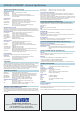
Bench or rack mounting
The QPX600D is housed in a 350mm (13¾”) wide case suitable for use on the
bench-top. Output and remote sense terminals are mounted on the rear panel
along with the analog and logic interface connectors and, on the QPX600DP,
the bus interface connectors.
The power supply is 3U high and a rack mounting kit (RM310A) is available as
an option.
Independent or simultaneous output control
The Both On and Both Off buttons are in
addition to the individual switches for
each output, and allow both outputs to
be turned on or off synchronously by a
single button press.
Synchronous switching of the outputs is of increasing importance for
circuitry which can lock-up or even be damaged if one voltage rail is
present without the other.
Power calculation
The meter for each output can be set to show the total power currently being
provided to the load (V x A) to a resolution of 0.1 watts.
Low resistance calculation
The meter for each output can
be set to show the equivalent
resistance of the load by
displaying voltage divided by
current.
Low resistance measurements
using a DMM utilise a low excitation current and suffer from thermal emf
errors and other low voltage effects.
This function enables low resistance measurements to be made at high
currents by using the remote sense terminals to create a four terminal
connection. This can give much more reliable results for certain component
types, such as magnetics, which operate at ampere levels.