
Information
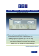

QPX600DP - USB, RS-232, GPIB & LAN
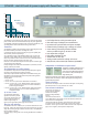
QPX600DP - comprehensive bus remote control
To meet a wide variety of needs, the QPX600DP adds a comprehensive
array of digital bus interfaces. RS-232, USB, GPIB and LAN (Ethernet)
with LXI support are all provided as standard.
Each of the digital bus interfaces provides full control of voltage,
current, output on/off and set-up, plus read-back of voltage, current
and status. The interfaces are at ground potential and are opto-isolated
from the output terminals.
The GPIB interface is compliant with IEEE-488.1
and IEEE-488.2. Currently GPIB remains the most
widely used interface for system applications.
An RS-232/RS-423 interface is provided for use with
legacy systems. This type of serial interface remains
in common useage and is perfectly satisfactory for
the control of power supplies because data speed is not an issue.
USB provides a simple and convenient means of
connection to a PC and is particularly appropriate
for small system use. A USB driver is provided
which supports Windows 2000, XP , Vista and Windows 7.
The LAN interface uses a standard 10/100 base-T
Ethernet hardware connection with ICMP and
TCP/IP Protocol for connection to a Local Area
Network or direct connection to a single PC. This interface supports LXI
and is highly appropriate for system use because of its scalable nature
and low cost interconnection.
The LAN interface is compliant with LXI class C. LXI
(LAN eXtensions for Instrumentation) is the next-
generation, LAN-based modular architecture
standard for automated test systems managed by
the LXI Consortium, and is expected to become the successor to GPIB in
many systems.
For more information on LXI and how it replaces GPIB, or operates along
side it, go to: www.tti-test.com/go/lxi
IVI Driver
An IVI driver for Windows is included. This provides support for common
high-level applications such as LabView*, LabWindows*, and HP/
Agilent VEE*.
* LabView and LabWindows are trademarks of National Instruments.
HPVEE (now Agilent VEE) is a trademark of Agilent Technologies.
* Windows is a trademark of Microsoft.
Other models in the QPX series
For those requiring only a single output power supply, the QPX1200 offers
1200 watts of PowerFlex performance from one output.
Go here for details: www.tti-test.com/go/qpx
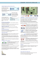
Graphic display for clarity and ease of use
The QPX600D incorporates two
high resolution graphic LCDs
capable of showing numbers and
text in a variety of sizes.
The standard display mode shows
voltage and current in large characters along with text annunciators such as
CV mode and Output On.
When settings are being
changed, a dual display of
parameters is used enabling
existing and new settings, or
actual and limit values to be
viewed simultaneously.
A similar arrangement is used
with smart metering for series or
parallel operation. More complex
functions are provided with text
prompts or complete selection
menus.
Current meter averaging
When measuring rapidly varying loads it can become difficult to get useful
readings from the current meter.
By selecting meter averaging, the reading is stabilised by averaging the last
four readings to reduce the speed and extent of the variation.
Numeric or rotary entry
Voltage and current levels can be set directly via the numeric keypad.
Alternatively settings can be changed via the jog wheel at user selectable
increments.
Multiple settings stores
Non-volatile stores are incorporated for rapid recall of voltage and current
settings and are useful for repetitive testing applications.
Separate stores are provided for each output.
OVP and OCP trips
Variable trips for over-voltage and over-current are provided on each output.
Unlike a limit setting, the trip setting turns the output off and provides a
different level of protection.
For example, when repetitively testing a unit which normally takes a peak
current of 10A, the current limit could be set to 11A and the OCP to 10.1A to
ensure that a faulty unit will trip the supply off and not be damaged by over
dissipation.
The output trip can also be activated by other fault conditions including over
temperature and remote sense mis-wiring. The cause of the trip is shown on
the display.
Analog and Logic interfaces
Both models incorporate analog interfaces for voltage
control of both output voltage and output current
(non-isolated, one for each output).
The control voltages are digitised to control the PSU and the scaling can be
selected as 0 to 5V or 0 to 10V for zero to full scale.
Monitor outputs for voltage and current are also provided, and can similarly be
selected as 0 to 5V or 0 to 10V.
An opto isolated logic control signal is provided for control of output on/off.
This can be menu selected as true = output on, or true = output off.
An opto isolated open-collector logic output signal is also available. This can
be menu selected as true or false for output enabled or disabled, current limit,
power limit, or any fault trip.