
User manual


2
Specification
General specifications apply for the temperature range 5°C to 40°C. Accuracy specifications apply
for the temperature range 18°C to 28°C after 1 hour warm-up with no load and calibration at 23°C.
Typical specifications are determined by design and are not guaranteed.
OUTPUT SPECIFICATION
Voltage Range:
0V to 60V
Current Range:
0A to 20A
Note: In manual operation, actual maxima for voltage and current are typically 1% greater that the figures
given above.
Power Range:
Up to 420W
Output Voltage Setting:
By coarse and fine controls.
Output Current Setting:
By single logarithmic control.
Operating Mode:
By single logarithmic control.
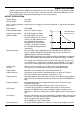
Constant voltage (CV) or constant
current (CC) with automatic cross-
over, provided that the power
demanded stays with the power
envelope, see graph. Outside of
this envelope the output becomes
unregulated.
Operating Ranges: Four selectable ranges: 60V/20A, 60V/7A, 20V/20A and Custom Limits.
Any V/I setting of the 60V/7A or 20V/20A ranges always falls within the
appropriate part of the Power Envelope.
The 60V/20A range permits any setting up to 60V and 20A but the output will
become unregulated if operated outside of the Power Envelope, see above.
The voltage and current limits of the Custom Limits range can be set to any
V
max
between 0.1V & 60V and I
max
between 0.01A and 20A. This facility is
most useful in limiting operation to a particular part of the Power Envelope.
Settings Lock:
(S-Lock)
Voltage and current settings can be locked by a single button press.
Lock accuracy is equal to meter accuracy (see Meter Specification)
Output Switch:
Electronic. Preset voltage and current displayed when off.
Output Terminals:
Front panel: Universal 4mm safety binding posts on 19mm (0·75”) pitch.
Rear Panel: Barrier strip connections (CPX400SA/SP only)
Output Sensing:
Switchable between local and remote. Remote connection by spring-loaded
push terminals on front panel and barrier strip on rear panel (CPX400SA /SP
only).
Output Protection:
Forward protection by Over-Voltage Protection (OVP) and Over-Current
Protection (OCP) trips.
Reverse protection by diode clamp for reverse currents up to 3A.
OVP Range:
1V to 66V set by front panel screwdriver adjustment or via the remote
interfaces (CPX400SP only). Setting resolution: 100mV. Response time:
Typically 1ms. Maximum voltage that should be applied across the terminals is
70V.
OCP Range:
Measure-and-compare over-current protection is implemented in firmware and
can only be set via the remote interface (CPX400SP only). Setting resolution:
10mA. Response time: typically 500ms.
For CPX400S/SA, OCP is fixed at 22A.
Over-temperature
The output will be tripped off if a fault causes the internal temperature to rise
CPX400S/SA/SP
Power Envelope