
User manual


3
Protection:
excessively.
Line Regulation:
Change in output for a 10% line change:
Constant voltage: <0.01% of maximum output
Constant current: <0.01% of maximum output
Load Regulation: Change in output for any load change within PowerFlex envelope, remote
sense connected:
Constant voltage: <0.01% of maximum output
Constant current: <0.05% of maximum output
Ripple & Noise
(20MHz bandwidth):
5mVrms max; typically <3mVrms, <15mV pk-pk, at maximum load, CV mode.
Transient Load
Response:
<250us to within 50mV of set level for a 5% to 95% load change.
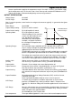
Voltage Programming
Speed
(CPX400SP only):
Maximum time required for output to settle within 1% of its total excursion
(for resistive load). Excludes command processing time.
Range and Setting 90% Load No Load 90% Load No Load
60V 7A
20V 20A
Up
Up
8ms
8ms
8ms
8ms
Down
Down
80ms
10ms
1.5s
1.2s
Temperature Coefficient:
Typically <100ppm/°C
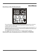
Status Indication: Output ON lamp.
Constant voltage mode lamp.
Constant current mode lamp.
Unregulated (power limit) lamp
Remote lamp (CPX400SP only)
LAN lamp (CPX400SP only)
Trip message on display.
METER SPECIFICATIONS
Meter Types:
Dual 4 digit meters with 10mm (0.39") LEDs. Reading rate 4Hz.
Meter Resolutions:
10mV, 10mA
Meter Accuracies: Voltage 0.1% of reading ± 2 digits
Current 0.3% of reading ± 2 digits
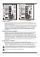
ANALOGUE REMOTE CONTROL (CPX400SA only)
Isolated inputs and non-isolated outputs to set voltage and current limit.
Isolated control input
scaling:
Rear panel control inputs (CV and CC) permit external 0V to 5V or 0 to10V
signals (with respect to the common Return) to set 0 to 100% of rated output
voltage and current. Inputs are protected against excess input voltages up to
60V. Isolation rating with respect to the output is 300V max.
Control input accuracy:
Voltage: 0.3% ±20mV. Input impedance 10kΩ.
Current: 0.5% ±50mA. Input impedance 10kΩ.
Control output scaling:
Set values of 0 to 100% of rated output voltage and current generate 0 to 5V
signals at the rear panel V
out
and I
out
outputs. Outputs are short-circuit
protected. These signals are referenced to the output control circuit and will
therefore be within ~1V of the positive output potential.