SMARTYCAM User Manual
SmartyCam User Manual Release 1.22 – firmware version 1.03.10 Dear Customer, SmartyCam, the new on board camera with data overlay, descends from the great AIM experience in developing data acquisition systems, mainly for motorsports applications.
SmartyCam User Manual Release 1.22 – firmware version 1.03.10 INDEX SmartyCam Quick Guide ................................................................................................... 5 1 – SmartyCam stand alone ....................................................................................................................... 5 2 – SmartyCam Slave (connected to an AIM device or the ECU via ECU Bridge) ................................ 6 Chapter 1 – SmartyCam: kit and optional items ..............
SmartyCam User Manual Release 1.22 – firmware version 1.03.10 INTRODUCTION SmartyCam features three different working modes. Stand alone: for non-motorsport applications or for motorsport applications whenever there is no ECU nor AIM data acquisition system/data logger (from here onward: logger). Slave connected to the vehicle ECU: for motorsport applications to sample data from the ECU with no need of additional sensors. In this case an AIM ECU Bridge is required. It is described in www.smartycam.
SmartyCam User Manual Release 1.22 – firmware version 1.03.10 SmartyCam Quick Guide SmartyCam is a very flexible product: it has been designed to fit the needs of an entry level user as well as these of a more professional motorsport driver. This flexibility implies the need for the user to configure the logger using the proper software. This quick guide includes all essential information for an easy and immediate SmartyCam use. Any other information is to be looked for in the indicated chapter/paragraph.
SmartyCam User Manual Release 1.22 – firmware version 1.03.10 2 – SmartyCam Slave (connected to an AIM device or the ECU via ECU Bridge) Install SmartyManager and Race Studio 2 software on the PC. The first one is needed to download new firmware versions from download area of www.smartycam.com and update SmartyCam functionalities, modify/add/delete overlay configurations – if desired – and download/see SmartyCam movies (Chapter 7).
SmartyCam User Manual Release 1.22 – firmware version 1.03.10 Chapter 1 – SmartyCam: kit and optional items SmartyCam package includes a complete kit that permits standard usage: in this manual some optional items are also shown, which can be useful in particular situations. 1.
SmartyCam User Manual Release 1.22 – firmware version 1.03.10 1.1.1 – SmartyCam part numbers As shown here below, SmartyCam part number is made up of 11 alphanumeric types, 7 of which already settled. Here follows explanation of how o determine the four remaining types. CAN or power cable selection: To use the on board camera in standalone mode a power cable is needed.
SmartyCam User Manual Release 1.22 – firmware version 1.03.10 1.2 – SmartyCam Bridges kits There are two available Briges for SmartyCam: ECU Bridge and RPM Bridge. 1.2.1 – ECU Bridge kits There are two available ECU Bridges, required to connect SmartyCam to the vehicle ECU. Their part number changes according to the communication protocol they are equipped with.
SmartyCam User Manual Release 1.22 – firmware version 1.03.10 1.3 – SmartyCam optional items: cables, external microphone and external GPS SmartyCam optional tools can be connected to it using the 4 pins and the 7 pins female connectors placed on the camera rear and shown here below. SmartyCam comes with dedicated cables that guarantee its proper working. • • The standalone kit comes with battery charge and power cable code V02566150.
SmartyCam User Manual Release 1.22 – firmware version 1.03.10 Chapter 2 – Data sampled by SmartyCam stand alone/slave As mentioned above, according to its working mode, SmartyCam provides different information. In Stand Alone mode, SmartyCam gets data from the integrated GPS and three-axial accelerometer: • • • • • • position; GPS speed; acceleration lap time; distance; track mapping.
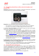
SmartyCam User Manual Release 1.22 – firmware version 1.03.10 Chapter 3 – SmartyCam connections The alternative SmartyCam modes (Stand Alone or Slave Expansion) require different connection procedures. 3.1 – Connecting SmartyCam stand alone SmartyCam stand alone can be connected in different ways: • connection to the external power only: use the 7-pins left connector highlighted in the image above and connect the power cables to a 12 Volts power source i.e. the vehicle battery. See appendix “B”.
SmartyCam User Manual Release 1.22 – firmware version 1.03.10 3.2 – Connecting SmartyCam Slave expansion with SMC1 Bridges In order to receive the info provided by the vehicle ECU without any additional logger, SmartyCam must be used in Slave expansion mode and connected via CAN to an ECU Bridge, using the 7-pins connector placed on the product rear. There are two available ECU Bridges version: • • code X90BGGPI2R for connection with aftermarket racing ECU with CAN or RS232 communication protocol.
SmartyCam User Manual Release 1.22 – firmware version 1.03.10 3.3 – SmartyCam in Slave expansion mode with AIM loggers SmartyCam can visualize data sampled by an AIM logger (EVO3 Pro/Pista, EVO4, MXL Strada/Pista/Pro05 or MyChron4) and by the vehicle ECU. In this case it is necessary to connect SmartyCam via CAN to the logger, using the CAN cable inserted into the 7-pins connector placed right of the product rear.
SmartyCam User Manual Release 1.22 – firmware version 1.03.10 Chapter 4 – How to charge SmartyCam battery SmartyCam is supplied with a 2000mAh 3.7 Volt rechargeable lithium battery. It can be charged using both the 7-pins right connector and the USB port highlighted in the image below. Connect SmartyCam to an external power source. The battery charge status is shown in any SmartyCam page. Below on the left the related field is shown. 4.
SmartyCam User Manual Release 1.22 – firmware version 1.03.10 Chapter 5 – SmartyCam configuration In order to configure SmartyCam data overlay2 SmartyManager software – exclusively developed by AIM – needs to be used. With SmartyManager it is possible to: • • • • change/add/cancel overlay configurations; download from www.smartycam.com “Updates” area a new firmware release and upgrade with it SmartyCam; download SmartyCam movies; see SmartyCam movies.
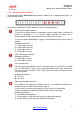
SmartyCam User Manual Release 1.22 – firmware version 1.03.10 Chapter 6 – How to use SmartyCam SmartyCam is managed using the three buttons placed above the display: 1,2 and 3 in the image here below on the left. The menu on the display shows the functions related to each button, close to the button itself.
SmartyCam User Manual Release 1.22 – firmware version 1.03.10 6.2 – How to switch SmartyCam on/off SmartyCam can be switched on in two ways: • • pressing “2” button, or connecting the external power cable to SmartyCam: as soon as the camera detects the 12V power on pin 3 the of 7 pins connector (see appendix “B”) it switches on. SmartyCam can be switched off in the following ways: • • • pressing “2” button any time “Off” option is available pressing “2” button for 10 seconds.
SmartyCam User Manual Release 1.22 – firmware version 1.03.10 6.3 – “Online” status (or mode) When SmartyCam is switched on, three options appear: • • • Rec Off Menu starts recording process (see paragraph 6.5) switches off the camera (see paragraph 6.
SmartyCam User Manual Release 1.22 – firmware version 1.03.10 6.4.2 – “SETTINGS” option As anticipated, clicking “SETTINGS” several options appear: LANGUAGE Chooses the desired language. In case of erroneous setting of Japanese language it is very simple to come back because “SETTINGS” and “LANGUAGE” labels are shown in red. TIME SETTING Chooses the time and date format, the time zone and enables or disables daylight saving time. Default setting is Greenwich Time.
SmartyCam User Manual Release 1.22 – firmware version 1.03.10 • • GPS CONF: loads the database of tracks to be shown in the dedicated area set with SmartyManager; the database has been transmitted to SmartyCam micro SD with SmartyManager; OVERLAY CONF: loads overlay database transmitted to SmartyCam micro SD through SmartyManager; If SmartyCam micro SD contains only one of these configuration files (only FILE NAME, only GPS CONF or again only OVERLAY CONF), that one is set.
SmartyCam User Manual Release 1.22 – firmware version 1.03.10 In all situations if GPS signal is “low” or “search”: please wait. Please note: if SmartyCam track option is in manual mode and a track is transmitted using SmartyManager software, the camera switches to “AUTO” mode. “SHOW” Shows the list of all tracks loaded: in bold the tracks that have a map associated, in grey the tracks that have only lap beacon coordinates. In “Manual” mode it is also possible to select the track to be used.
SmartyCam User Manual Release 1.22 – firmware version 1.03.10 6.5.2 – Automatic recording • • In slave mode (SmartyCam connected to an AIM logger or Bridge): the logger transmits a start/stop recording input to SmartyCam, as soon as it detects RPM or a speed higher/lower than 10 km/h. “Stop recording” input SmartyCam receives from the master has a time delay set through “STOP” option placed on bottom of “REC STRATEGY” page: 5 , 20 or 60 sec, 2 or 5 min.
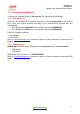
SmartyCam User Manual Release 1.22 – firmware version 1.03.10 Chapter 7– Downloading data and viewing SmartyCam videos 7.1 – Downloading data SmartyCam can download data via USB (connecting the on board camera to the PC using the cable provided with the kit), or through the micro SD placed in the SmartyCam rear, which will have to be inserted in the PC USB port. It is recommended to use exclusively a 2.0 USB port.
SmartyCam User Manual Release 1.22 – firmware version 1.03.10 Chapter 8 – SmartyCam Maintenance SmartyCam does not require any particular maintenance. Warning: it is strongly recommended not to open the camera. Periodically check www.smartycam.com for software and/or firmware updates; a recommended option is to subscribe to the www.smartycam.com newsletter to receive all updates in real time.
SmartyCam User Manual Release 1.22 – firmware version 1.03.10 Appendix “A” – Technical specifications SmartyCam measures (in mm) Accelerometer three-axial ±5G Internal battery 2.000 mAh 3.
SmartyCam User Manual Release 1.22 – firmware version 1.03.10 Appendix “B” – SmartyCam Pinout N. rev. / Rev. N. Descrizione / Description Firma / Signature Data / Date Contr. da / Ckd. by EXT GPS SMARTYCAM PINOUT 7 1 2 3 6 5 4 EXT Binder Pinout Contact insertion view 1 2 3 4 5 6 7 Q.tà/Q.ty Rif. / Ref. Progettato da / Designed by 4 1 3 2 GPS Binder Pinout Contact insertion view 1 2 3 4 CAN+ GND +Vb CANVbext GND Mic2+ CAN+ GND +Vb CAN- Material / Material Contr. da / Ckd. by N.