
Blower Operating Manual


www.airkinglimited.com
111597005 New 3-07
2. Using the included 8-32 screws and washers, mount the blower in place
and tighten all screws. Confirm that the blower is securely seated in place
and there are no air gaps around the blower gasket.
3. Plug both the 3 wire and 4 wire quick connect cords from the blower into
the appropriate receptacles located on the inside front of the hood canopy.
These cords will only fit into the receptacles one way (Figure 2).
SECTION 3
Installation into 10" High Canopy
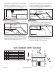
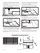
1. Remove the rear bottom plate of the hood canopy. It is secured in place
with a screw and washer on either side (Figure 3).
2. Lift blower up into the hood canopy and slide the keyhole slots in the blower
mounting flange over the two studs of the hood. Slide the blower into place
and tighten the hex nuts on the mounting stud while lining up the 8 holes
in the blower mounting flange to the 8 screw studs of the hood (Figure 1).
3. Using the included 8-32 screws and washers, mount the blower in place
and tighten all screws. Confirm that the blower is securely seated in place
and there are no air gaps around the blower gasket.
2 of 8
4. Plug both the 3 wire and 4 wire quick connect cords from the blower into
the appropriate receptacles located on the inside front of the hood canopy.
These cords will only fit into the receptacles one way (Figure 2).
5. Reinstall the rear bottom plate by fitting the back edge of the plate into the
channel located on the back of the hood and reinstalling the two screws
and washers removed in
Step 1
(Figure 4).
SECTION 4
Finishing the Installation
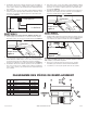
1. Install the included fuse into the electrical panel by turning the fuse cap
counter clockwise and pulling out. Insert the included 1/4" x 1-1/4" time
delay fuse in the holder and reinstall into the panel (Figure 5).
NOTE: If you need to replace the fuse, replace with a 1/4" x 1-1/4" Bussman
MDA-3 or equivalent 3 amp, 250V ceramic, time delay fuse only.
2. Refer to the hood instruction manual to complete the installation, for
maintenance, and before restoring power.
3. The blower is covered under the range hood’s warranty.
Receptacles
Figure 2
Blower
REPLACEMENT PARTS DIAGRAM
# Qty. Description Replacement Part #
1 1 Blower Assembly 5S1136063
2 1 Blower Gasket 5S1136100
3 8 Grommet 5S1136101
4 8 Washer 5S1136102
5 8 8-32 Screw 5S1136103
6 1 Capacitor 5S1136104
7 1 Screw 5S1136105
8 1 Fuse 5S1136106
5
1
2
3
6
7
4
Fuse
Figure 5
Cap
8
Channel
Figure 4
Screw
Bottom Plate
Washer
Figure 3
Screw
Bottom Plate
Washer