Kits 57268 and 57284 Ford F-150 MN-957 • (011502) • ERN 8111/8112 2 & 4 Wheel Drive INSTALLATION GUIDE For maximum effectiveness and safety, please read these instructions completely before proceeding with installation. Failure to read these instructions can result in an incorrect installation.
TABLE OF CONTENTS Installation Diagram. . . . . . . . . . . . . . . . . . . . . . . . . . . . . . . . . . . 2 Hardware and Tools Lists . . . . . . . . . . . . . . . . . . . . . . . . . . . . . . . . . . . . . . . . . . . . . . . . . . . 3 Introduction. . . . . . . . . . . . . . . . . . . . . . . . . . . . . . . . . . . . . . . . . . 4 Important Safety Notice . . . . . . . .
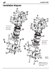
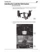
LoadLifter 5000 Installation Diagram Left-hand side (driver-side), Four-wheel drive model. Left-hand side (driver-side), Two-wheel drive model. fig. 1 NOTE: Carriage bolt (N) is inserted from the bottom in two-wheel drive models.
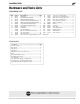
LoadLifter 5000 Hardware and Tools Lists HARDWARE LIST Item Part # Description................................ Qty A B C D E F1 F2 G H I J K L M 01531 07181 07274 07179 07280 03023 03024 58439 11951 21848 17203 18427 18444 17102 Clamp bar............................................2 Left-hand frame bracket......................1 Right-hand frame bracket....................1 Left-hand air spring upper bracket......1 Right-hand air spring upper bracket....1 Lower bracket (2WD models)..............
LoadLifter 5000 Introduction The purpose of this publication is to assist with the installation, maintenance and troubleshooting of the LoadLifter 5000 air spring kit. LoadLifter 5000 utilizes sturdy, reinforced, commercial grade single or double, depending on the kit, convolute bellows. The bellows are manufactured like a tire with layers of rubber and cords that control growth.
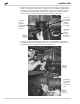
LoadLifter 5000 Installing the LoadLifter 5000 System GETTING STARTED 1. Lift the vehicle up and support the frame with jack stands. Leave enough room to drop the axle down low enough to install the air spring assemblies into position between the axle and the frame (fig. 2). fig. 2 2. In order to install the assemblies, the jounce bumpers and cups will need to be removed (fig. 3). Figure 4 shows the driver-side frame with the jounce bumper removed. fig. 3 fig.
LoadLifter 5000 3. Install the left-hand (driver-side) frame bracket (B) onto the frame, ensuring that the flange is on the inside of the frame. The large hole under the bracket will be behind the axle as shown (fig. 5). Attach with the M10 hex cap screw (P) and lock washer (S), making sure that the bracket is parallel to the ridge that is under the frame rail. Torque to 35 lb.-ft. (47Nm). Repeat for the right-hand (passenger) side. The large hole in the upper bracket will be behind the axle.
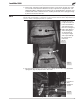
LoadLifter 5000 5. On the front of the driver-side spring perch there is a hole and a slot (fig. 8). In order to mount the lower bracket it will be necessary to tap the hole using the 5/16” selftapping bolt (M) by starting the bolt making sure it is perpendicular to the perch. Use a ratchet and socket to drive the bolt in, creating the threads in the spring perch (fig. 9). Remove the bolt for later use.
LoadLifter 5000 7. Index the brake line/ABS bracket alignment tabs through the lower bracket on the back of the spring perch, and reattach using the M8 flange bolt (Q) provided (fig. 11). Also, attach the emergency brake line bracket on the front of the passenger-side spring perch in the same manner. Finish by installing the 5/16” bolt previously used to tap the forward spring perch hole and LEAVE ALL HARDWARE LOOSE AT THIS TIME. Q fig. 11 8.
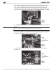
LoadLifter 5000 10. Once the clamp bar is snug to the axle, torque all the spring perch hardware to 20 lb.-ft. (27Nm). Then torque the axle clamp hardware to 15 lb.-ft. (20Nm). Figures 1417 (four-wheel drive) and 18-21 (two-wheel drive) show the lower bracket once it has been mounted to the axle. Four-wheel drive models with lower bracket installed: fig. 14 fig. 15 Driver-side rear view Passenger-side rear view fig. 16 fig.
LoadLifter 5000 ASSEMBLING THE AIR SPRINGS ASSEMBLIES 1. Set a roll plate (H) over the air spring (G). NOTE The radiused (rounded) edge of the roll plate (H) will be towards the air spring, so that the air spring is seated inside both roll plates. 2. Install the swivel fitting (I) into the top of the air spring finger-tight plus one-and-a-half turns (fig. 22). Repeat for both air springs. I H fig. 22 3.
LoadLifter 5000 INSTALLING THE AIR SPRING ASSEMBLIES 1. With the axle dropped low enough to put the assemblies into position, set the leftand right-hand assemblies on the lower brackets (previously installed), making sure that the fittings are on the outside of the frame as shown. Lift and attach the air spring upper bracket to the frame bracket using two 3/8” carriage bolts (O), two flat washers (L) and two nylon lock nuts (R) (figs. 25, 26). Torque hardware to 20 lb.-ft. (27Nm).
LoadLifter 5000 3. Raise the suspension back up just enough so that the air spring comes in contact with the roll plate and the lower bracket. Align the holes again and attach the lower air spring to the lower bracket using two 3/8” bolts (J), two lock washers (K) and flat washer (L) (fig. 28). Repeat for the opposite side. 4. Raise the axle all the way up and adjust the air spring by pushing it forward in the slot. Make sure it is aligned so that it is perpendicular to the upper and lower bracket.
LoadLifter 5000 Inside view of right-side mounted assembly fig. 31 FINISHING THE INSTALLATION For 2WD models it will be necessary to trim the Brake/ABS line holder that is closest to the axle so that it does not chafe on the driver side bellows. 1. Trim the outboard open slot on the plastic line holder off using a hack saw or side cutters (fig. 32). Finished photo shown in fig. 33. Trim Brake/ABS line holder off here. fig. 32 fig.
LoadLifter 5000 Installing the Air Lines This section explains how to set up the air spring kit to be controlled with Schrader valves and a separate compressed air source. An on-board air compressor system allows for hassle-free control of the air springs. Learn more about Air Lift control systems at www.airliftcompany.com/products/compressor-systems. 1. Choose a convenient location for mounting the inflation valves (fig. 34). Popular locations for the inflation valve are: a. The wheel well flanges b.
LoadLifter 5000 TIPS FOR INSTALLING AIR LINES When cutting air lines, use a sharp knife or a hose cutter and make clean, square cuts (fig. 36). Do not use scissors or wire cutters because these tools may deform the air line, causing it to leak around fittings. Do not cut the lines at an angle. Do not bend the 1/4” hose at a radius of less than 1” or bend the 3/8” hose at a radius of less than 1 1/2”. Do not put side load pressure on fitting.
LoadLifter 5000 Before Operating CHECKING FOR LEAKS 1. Inflate the air spring to 30 PSI. 2. Spray all connections and the inflation valves with a solution of 1/5 liquid dish soap and 4/5 water. Spot leaks easily by looking for bubbles in the soapy water. 3. After the test, deflate the springs to the minimum pressure required to restore the system to normal ride height. Do not deflate to lower than 5 PSI. 4. Check the air pressure again after 24 hours. A 2-4 PSI loss after initial installation is normal.
LoadLifter 5000 INSTALLATION CHECKLIST Clearance test — Inflate the air springs to 75-90 PSI and make sure there is at least 1/2” clearance from anything that might rub against each sleeve. Be sure to check the tire, brakes, frame, shock absorbers and brake cables. Leak test before road test — Inflate the air springs to 75-90 PSI and check all connections for leaks. All leaks must be eliminated before the vehicle is road tested.
LoadLifter 5000 Product Use, Maintenance and Servicing Minimum Recommended Pressure Maximum Air Pressure 5 PSI 100 PSI MAINTENANCE GUIDELINES NOTE By following the steps below, vehicle owners will obtain the longest life and best results from their air springs. 1. Check air pressure weekly. 2. Always maintain normal ride height. Never inflate beyond 100 PSI. 3.
LoadLifter 5000 TUNING THE AIR PRESSURE Pressure determination comes down to three things — level vehicle, ride comfort and stability. 1. Level vehicle If the vehicle’s headlights are shining into the trees or the vehicle is leaning to one side, then it is not level (fig. 38). Raise the air pressure to correct either of these problems and level the vehicle. 2. Ride comfort If the vehicle has a rough or harsh ride it may be due to either too much pressure or not enough (fig. 39).
LoadLifter 5000 Troubleshooting Guide PROBLEM CAUSE SOLUTION System won’t maintain pressure overnight. Improperly installed air line, air line has holes or cracks. Leak test the air line connections, the threaded connection into the air spring, and all fittings in the control system. Air spring or air line leak. Fitting seal or air line is compromised. Check to make sure air lines are seated in connectors. Inspect fittings with soapy water. Trim hose or re-seal fitting.
LoadLifter 5000 Limited Warranty and Return Policy Air Lift Company provides a limited lifetime warranty to the original purchaser of its Load Support products, that the products will be free from defects in workmanship and materials when used on cars and trucks as specified by Air Lift Company and under normal operating conditions, subject to the requirements and exclusions set forth in the full Limited Warranty and Return Policy that is available online at www.airliftcompany.com/warranty.
Need Help? Contact Air Lift customer service department by Contact AirCompany Lift Company customer service calling (800) 248-0892. department by the calling For calls from outside USA or (800) Canada,248-0892. dial (517) 322-2144. For calls from outside the USA or Canada, dial (517) 322-2144. Thank you for purchasing Air Lift products — the professional installer’s choice! Air Lift Company • 2727 Snow Road • Lansing, MI 48917 or P.O.