INTRODUCTION This airless paint sprayer is a time tested, slow stroking pump - contractor approved to meet the demanding needs of the professional painting contractor. SPECIFICATIONS AIRLESSCO ALLPRO GPM PRESSURE MAX. TIP SIZE 8 SERIES SL810 810E .81 3000 .021 (1 gun)- .017 (2 guns) 10/11 SERIES SL1100 1000E 1.1 3000 .033(1 gun)- .
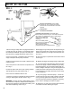
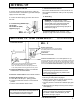
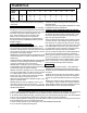
HOW TO FLUSH FIG. 1 REMOVE SPRAY TIP FIG. 3 ENGAGE GUN SAFETY LATCH (LOCK GUN) as per gun instruction manual. metal pail FIG. 2 Pressure Control Knob: used to adjust pressure only. Turn clockwise to increase pressure and counterclockwise to decrease pressure. On/Off Switch Thermal Overload Switch Prime/Pressure Relief Valve (Prime/PR Valve) Used to relieve pressure from gun, hose & tip and to prime the unit when in OPEN position.
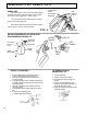
SETTING UP 1. Connect the Hose and Gun 3. Check the Electrical Service a. Remove the plastic cap plug from the outlet connector and screw a conductive or grounded 3000 psi spray hose onto fluid outlet. Be sure the electrical service is 120 V, 60 HZ AC 15 amp minimum and that the outlet you use is properly grounded. b. Connect an airless spray gun to the other end of the hose. 4. Grounding 2. Fill the Packing Nut/Wet Cup 1/3 full with Throat Seal Oil (TSO) supplied. (Fig. 4) FIG.
SETTING UP AND STARTING 6. Adjusting the Pressure a. Turn the pressure control knob clockwise to increase and counterclockwise to decrease pressure. b. Always use the lowest pressure necessary to completely atomize the material. CAUTION: Operating the sprayer at higher pressure than needed wastes material, causes early tip wear and shortens sprayer life. c. If more coverage is needed use a larger tip rather than increasing the pressure. d. Check the spray pattern.
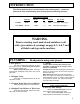
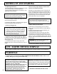
WARNINGS MEDICAL ALERT - Airless Spray Wounds If any fluid appears to penetrate your skin, get EMERGENCY MEDICAL CARE AT ONCE. DO NOT TREAT AS A SIMPLE CUT. Tell the doctor exactly what fluid was injected. NOTE TO PHYSICIAN: Injection in the skin is a traumatic injury. It is important to treat the injury surgically as soon as possible. DO NOT DELA Y treatment to research toxicity. Toxicity is a concern with some exotic coatings injected directly into the blood stream.
WARNINGS PRESSURE RELIEF PROCEDURE To avoid possible serious bodily injury, including injection, always follow this procedure whenever the sprayer is shut off, when checking or servicing it, when installing, changing or cleaning tips and whenever you stop spraying or when you are instructed to relieve the pressure. 1. Engage gun safety latch. Refer to separate instruction manual provided with your gun on its safety features and how to engage safety latch. 2. Turn unit off and unplug from electrical outlet.
WARNINGS UL RECOMMENDATION FOR MINIMUM GAUGE EXTENSION CORD AMPERAGE RATING RANGE 5-6 6-8 8 - 10 10 - 12 VOLTAGE 120 120 120 120 25 50 100 150 200 250 300 400 500 18 18 18 16 16 16 14 14 12 12 12 10 12 10 10 8 10 10 8 8 10 8 8 6 8 6 6 6 8 6 6 4 6 6 4 4 Always follow recommended pressure and operating instructions. ALWAYS use approved high pressure fittings and replacement parts. ALWAYS ensure fire extinquishing equipment is readily available and properly maintained.
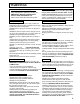
AIRLESSCO 007 SPRAY GUN SPRAY GUN Attach spray gun to airless unit and tighten fittings securely. Set the gun safety latch.(Also may be called gun safety lock or trigger lock) * Refer to Fig. A. GUN SAFETY LATCH IN LOCKED POSITION GUN SAFETY LATCH * The gun safety latch should always be set when the gun is not being triggered. Read all warnings and safety precautions supplied with the spray gun and in product manual. FIG.
SPRAY TECHNIQUE Good Spray Gun Technique is at the core of any spray paint operation. Operator skill and efficiency is as important as good equipment and good paint. Good spray technique is a skill that can be quickly learned by following these simple instructions. If you are not familiar with spraying techniques, we recommend that you study this section of your manual and practice the proper technique on pieces of cardboard or a suitable surface.
SPRAY TECHNIQUE TOTAL SPRAYGUN MOVEMENT - arm movement - full sweep TRIGGER POINT TRIGGER POINT e t Strok al Pain ctu The A T It is important to "trigger" the gun after gun movement (arm movement) has started and release trigger (shut gun off) before gun movement ends. Gun movement is always longer than actual paint (spray) stroke. In that manner, even blending and uniform paint coat thickness is achieved over the entire surface.
AIRLESS SPRAY GUN OPERATION DEFECTS CAUSE CORRECTION Coarse spray Low pressure Increase the pressure. Excessive fogging (overspray) High pressure Material too thin Reduce the pressure to satisfactory pattern distribution. Use less thinner. Pattern too wide Spray angle too large Use smaller spray angle tip.
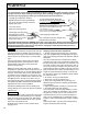
SPRAY TIP SELECTION Spray tip selection is based on paint viscosity, paint type, and job needs. For light viscosities (thin paints), use a smaller tip; for heavier viscosities (thicker paints), use a larger tip size. TIP SELECTION CHART REV -TIPS (P.N. 560-XXX) FLAT TIPS (P.N. 570-XXX) For sizes not shown, call factory for availability. Spray tip size is based on how many gallons of paint per minute can be sprayed through the tip.
REGULAR MAINTENANCE 1. Always stop the pump at the bottom of its' stroke when you take a break at the end of the day . This helps keep material from drying on the rod and damaging the packings. 2. Keep the displacement pump packing nut/wet cup 1/3 full of TSO at all times. The TSO helps protect the packings and rod. 3. Inspect the packing nut daily. It should be tight enough to stop leakage, but no tighter . Overtightening will damage the packings.
TROUBLESHOOTING PROBLEM CAUSE The fluid supply is low or empty. Refill the supply container. Air entrapped in the fluid pump of hose. Check for loose connections on the siphon assembly, tighten, then reprime pump. The wet cup is loose. Tighten just enough to stop leakage. The throat packings are worn or damaged. Replace the packings. See page 17 - 18. Piston Rod Worn. Replace piston rod. See page 17 - 18. The motor operates, but the paint pump doesn't The pressure setting is too low.
SERVICING FLUID PUMP Note: Check everything in the Troubleshooting Chart before disassembling the sprayer. FLUID PUMP DISCONNECT 1. 2. 3. 4. 5. 6. Flush out the material you are spraying, if possible. Follow the Pressure Relief Procedure on Page 6. Stop the pump in the middle of down stroke. Remove the suction tube and fluid hose (if so equipped) from the fluid pump. Remove 2 retaining rings and slip the sleeve of the coupling down and remove both coupling halfs.
SERVICING UPPER & LOWER CHECK VALVES LOWER CHECK VALVE (SEE FIG. 7 & 9) 1. Screw the lower check valve nut (187-018) out of the pump housing (187-313) containing intake seat support (187-017). 2. Remove the intake seat (187-065), O-ring (187-034), intake ball (187-020) and retainer (187-016). 3. Clean all parts and inspect them for wear or damage, replacing parts as needed. Old "O" rings should be replaced with new ones. 4. Clean inside of pump housing (187-313). 5.
V - PACKING REPLACEMENT V-PACKING REPLACEMENT KIT SEVERE DUTY- PART NO. 187-040 Contains: Leather & Plastic Packings, PTFE & Viton O-Rings, Balls & Upper Ball Stop & plastic dual sided female adaptor & Larger Plastic Male Glands. V-PACKING REPLACEMENT KIT ALL PTFE - PN 187-042 FIG. 8 GLAND KIT - PN 187-064 V-PACKING REPLACEMENT INSTRUCTIONS 1. Remove the fluid pump as per the "Fluid Pump Disconnect" instructions page 15. 2. Unscrew and remove the lower check valve per instructions page 16. 3.
FLUID PUMP - 187-310 FIG. 9 106-018 187-046 106-014 (opt.) 187-016 187-047 187-315 187-020 106-013 187-313 187-037 106-012 106-017 187-311 187-026 187-029 187-059 187-030 187-065 187-018 187-058 187-060 187-017 187-022 115-022 187-025 187-029 301-094 187-059 187-021 106-016 187-031 106-015 187-037 141-010 187-061 187-021 REASSEMBLY 11. Lubricate leather packings in lightweight oil for 10 minutes prior to assembly. 12. Remove masking tape from piston. (if used) 13.
REPLACEMENT OF BELT/BELT ADJUSTMENT NOTE: The Cog Belt System does not require alignment. When upper sheave is placed on motor shaft it is pushed on until a positive stop DEFLECTION is reached. The set screws (Fig. 15, Item 30) are then loctited. The lower pulley is placed on gearbox and held in place with keyway and snap ring (Fig. 15, Item 18) The flange on upper sheave holds the belt in alignment and the belt self aligns on lower pulley eliminating having to align. FIG.
MANIFOLD FILTER - PN 111-200-99 FIG. 13 1 2 3 4 5 6 7 8 8 10 9 FIGURE 13 PARTS LIST ITEM 1 2 3 4 5 6 7 8 9 10 * 20 PART NO.
PAINT SYSTEM - PN 301-454 FIG. 14 5 8 9 7 6 15 4 10 12 11 13 1 3 14 2 ITEM NO. 1 2 3 4 5 6 7 8 9 10 11 12 13 14 15 FIG. 14 PARTS LIST PART NO. DESCRIPTION 100-109 301-308 301-318 111-037 331-294-99 100-028 100-180 301-348 111-200 100-004 100-109 100-160 100-312 331-103 167-016 Nipple 1/4 Hose (2) Pressure Control Ass'y Screw (8) Sensor Plug 1/4 Prime/Pres.
COMPLETE SPRAYER FIG. 15 57,58,59 31 29 65 26 27 28 14 15 13 63 60 30 33 32 41,55,56,61,62 12 20 7 34, 42 6 35 8 5 4 8 3 43 9 11 10 16 17 45 44 22 66 19 18 21 25 1 23 24 2 46 47 48 54 52, 53 51 22 Optional Suction Assy.
COMPLETE SPRAYER PARTS LIST ITEM NO. 1 2 3 4 5 6 7 PART NO.
SUPPLEMENTAL 230 VOLT PARTS LIST 24 MODEL MOTOR & PART NO. FUSE & PART NO. BOARD 8 SERIES 1 HP - P.N. 301-058A 12 AMP P.N. 331-165 P.N. 301-364 10/11 SERIES 1.25 HP - P.N. 301-255A 15 AMP - P.N. 331-256 P.N.