Host RJ-11 IP Gateway User Guide Version 1.02 - February 2007 Copyright © 1993-2007 AirLink Communications, Inc. All rights reserved.
Contents Introduction . . . . . . . . . . . . . . . . . . . . . . . . . . . . . . . . . . . . . . . . . . . 3 Host RJ-11 IP Gateway Features 4 Installation . . . . . . . . . . . . . . . . . . . . . . . . . . . . . . . . . . . . . . . . . . .
Contents System Log 33 Port Status 33 OS and Network Information Log Files and Settings 35 Commands 34 36 Ping 36 Reset/Reboot 37 Specifications 38 Physical Dimensions 38 Connections 38 Phone and Modem standards 38 Environmental 38 Optional Mounting Bracket 39 AT Commands 40 Response Codes 42 Modem Signal Behavior Phone Numbers 43 Port Settings 44 43 Warranty Terms and Conditions 45 Standard Software Warranty 45 One Year Standard Equipment Warranty Remedy 45 WARRANTY DISCLAIMER 46 LIMITATION OF LIA
CHAPTER 1 Introduction Many existing meters, data loggers, RTU's, PLC's, point-of-sale, and other remote devices only have physical interfaces designed to access the telephone network. They do not have serial or Ethernet ports. They currently use analog cellular or standard phone lines to connect in circuitswitched mode for data transfer. Analog cellular phone service is being discontinued.
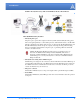
Introduction FIGURE 2. Host RJ-11 Gateway with an AirLink Raven-E and a Modem Router Host RJ-11 IP Gateway Features • One RJ-11 phone port The phone port is a phone line designed to function just like standard wall-jack analog phone line. It is designed primarily to connect dial-up devices, with internal modems, to the RJ-11 IP Gateway, which then routes data from the devices over the network.
CHAPTER 2 Installation Configuring the Host RJ-11 IP Gateway to work with your network or Raven-E and your RJ-11 equipped device is easy. This chapter covers a basic configuration. Caution: The Host RJ-11 IP Gateway’s RJ-11 port (labeled “Phone”) should not be connected into the Public Switched Telephone Network. This port is the emulation for a Phone that you would have been using with your device.
Installation If you will be connecting the Host RJ-11 IP Gateway to a Raven-E, you will need a cross-over Ethernet cable to configure your Raven-E unless your computer’s Ethernet port is auto-sensing. The Host RJ-11 IP Gateway has an auto-sensing Ethernet port, you can use either a cross-over cable or a straight-through Ethernet cable to connect the Host RJ-11 IP Gateway to the Raven-E or your computer.
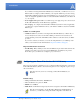
Installation Configuring the Raven-E 1. Connect your Raven-E directly to the Ethernet port on your computer and to power. 2. Start Wireless Ace and connect to your modem. Start > All Programs > AirLink Communications > Wireless Ace 3G > Wireless Ace 3G A. Click on Connect. B. Select UDP. C. Type in the modem’s local IP (default is 192.168.13.31). D. Type in the modem’s password (default 12345) FIGURE 1. 3.
Installation Private Mode Configure the Raven-E for Private Mode. In this mode, the modem communicates with the Host RJ-11 IP Gateway via a static local IP address. If the modem and the Host RJ-11 IP Gateway are going to be on a LAN with other computers and devices you may want to use Private Mode. On a LAN, a DHCP server other than the modem may give the Host RJ-11 IP Gateway an IP address to which the modem would not know to send its messages. a. Set the *HOSTPRIVMODE to 1. b.
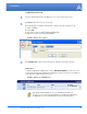
Installation FIGURE 5. B. Wireless Ace: Status Note the IP address listed in the Value column for the command *NETIP. For *NETSTATE, “Network Ready” means your modem is connected on the cellular network and waiting for connections. “Network Dormant” means the modem is connected and waiting for connections but the connection has been idle. In either state, the modem is ready for the steps in the next section. 6.
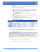
Installation FIGURE 6. 3. optional Port Utility Configure a temporary IP address for configuring the Host RJ-11 IP Gateway. A. Double-click on the [Click to Assign] for the discovered device (if an IP addess is listed in that column, double-click on the IP address if you need to change it). B. Type in an IP address. It’s recomended that you use 192.168.1.3. C. Press Enter to save the address. If the Host RJ-11 IP Gateway is not displayed in step 2, you will need to manually add the device. A.
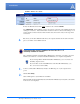
Installation 4. Temporarily change your computer to a static IP address to configure the Host RJ-11 IP Gateway. A. Open the properties for your network connection. Start>Control Panel>Network Connections, right-click on your local area connection, and select Properties. FIGURE 8. Local Area Connection B. Select Internet Protocol (TCP/IP) and click on Properties. C. Note the current settings (so you can return to them when you finish). FIGURE 9. TCP/IP Properties D.
Installation Note: When you have completed configuring the Host RJ-11 IP Gateway, you will want to reconfigure the IP address on your computer to how it was configured before you started these steps. Use the directions in this step to reset the configuration. Configuring the IP Address and Interface Port of the Host RJ11 IP Gateway Host RJ-11 IP Gateway Defaults • • • • • Phone port: 8 data bits, no parity, and 1 stop bit (8N1). Protocol: American/Bell 212A. Maximum baud: 2400. DHCP client: disabled.
Installation FIGURE 11. 3. Host RJ-11 IP Gateway Interface Select Network Settings from the menu on the left. FIGURE 12. Host RJ-11 IP Gateway: Network Settings DHCP Mode In DHCP Mode, the Host RJ-11 IP Gateway will receive its IP address from the modem. The IPv4 Address and the IPv4 Netmask should be listed as 0.0.0.0.
Installation FIGURE 13. RJ-11 IP Gateway: Network Interface Settings Static IP Mode If the Host RJ-11 IP Gateway is going to be on a LAN, you many wish to set a static IP address. Use this mode only if you have configured Private Mode for the modem. The default for the Host RJ-11 IP Gateway is a static IP address of 192.168.1.3. FIGURE 14. Host RJ-11 IP Gateway: Network Interface Settings 192.168.1.3 255.255.255.0 4. A. Set the IPV4 Address to match the *HOSTPRIVIP in step 3 of the previous section.
Installation FIGURE 15. Host RJ-11 IP Gateway: Serial Settings 8 None 1 For more information on these settings, refer to page 21. Note: For most configurations, the default settings are best. Change these parame- ters only if you know the device you will be connecting to the Host RJ-11 IP Gateway requires special settings. 5. Click on the Reset/Reboot menu option for the IP Address configuration and any changes to the serial port settings to take effect. FIGURE 16.
CHAPTER 3 Hardware Designed for simplicity, the Host RJ-11 IP Gateway hardware has few complicated parts. Connectors and Reset button The Reset button is recessed. To reset the connection, using an unbent paperclip or other narrow, blunt tip, press and quickly release the reset button. To reset the configuration to the factory default, press and hold the reset button until you see the appropriate alternating light sequence. FIGURE 1.
Hardware FIGURE 3. Host RJ-11 IP Gateway Top Panel (not to scale) • STATUS - Indicates the overall status of the device. TABLE 1. Status - Normal Operation LED Condition Description Blinking Yellow The Host RJ-11 IP Gateway is starting up. Solid Green The Host RJ-11 IP Gateway is obtaining an IP address from the modem. Blinking Green The Host RJ-11 IP Gateway has an IP address and is operating normally. Off No power to the Host RJ-11 IP Gateway. TABLE 2.
Hardware TABLE 3. Status - Error Conditions Alternating Green/Yellow The current configuration is corrupt and the factory default configuration is being used Solid Red The Host RJ-11 IP Gateway has encountered a fatal error, contact technical support for assistance. • ETHERNET - Indicates the status of the Ethernet connection (RJ-45 port). TABLE 4. Ethernet LED Condition Description Solid Green The Ethernet link is available and idle. Green/Yellow Blinking Network traffic is detected.
CHAPTER 4 Configuration Settings and Commands The Host RJ-11 IP Gateway can be configured to handle a variety of devices which need to connect to an RJ-11 port. If you’re using a Raven-E with the Host RJ-11 IP Gateway, for configuration options for your Raven-E, refer to the modems’s user guide. All user guides are available on the AirLink website: http://www.airlink.com/support.
Configuration Settings and Commands FIGURE 2. Host RJ-11 IP Gateway Web Browser-based Interface Service Configuration Most of the Service Configuration menu options deal with the RJ-11 port. Welcome The Welcome screen is the first page displayed when you connect to the Host RJ-11 IP Gateway. Current settings and status are shown in a table. FIGURE 3.
Configuration Settings and Commands • Ethernet Address: MAC Address of the Host RJ-11 IP Gateway. • IP Address: The current IP Address of the Host RJ-11 IP Gateway and how the IP address was assigned (in the example, a Raven-E in Public Mode used DHCP to give the Host RJ-11 IP Gateway the IP addressed assigned by the cellular network). • IP Netmask: The current subnetmask of the Host RJ-11 IP Gateway and how the device obtained it.
Configuration Settings and Commands • With Modem Signal Loopbacks, the Host RJ-11 IP Gateway eliminates the use of specialized cables required to change signal types and directions by performing the loopback of signal types to other signal types internally. • NativeCOM, (or any RFC-2217 Telnet client with COM-PORT-OPTION support) overrides the baud rate, size, parity, stop bits and flow control parameters.
Configuration Settings and Commands • Modem Service: Enables modem emulation on both the incoming and outgoing network connections. The target peer (specified in the Phone Number Translation table and configured in the Protocol Settings page) determines the type of outgoing connection that will be made. • Outgoing Network Connection: Enables an outgoing connection to the specified host. • Outgoing Telnet Connection: Enables an outgoing telnet connection to the specified host.
Configuration Settings and Commands Once you have created and saved an entry in the table, a link to the associated entry on the Protocol Settings page appears on the right. If the protocol is not yet defined, this link, “Define protocol”, will create a new entry on the Protocol Settings page, otherwise the link will be “Edit protocol”. The translation table screen allows you to add up to 5 new entries at a time. A total of 64 entries may be configured including the default entry.
Configuration Settings and Commands imposes limits on source TCP ports then you may need to set this to something specific. Note that if you specify something other than 0, you will be limited to only 1 TCP pipe at-a-time for any given destination port. Protocol Settings For each host (peer) you will make an outgoing connection to, you need to specify the protocol options used for that host. For each host, select the Host from the “Edit settings for a different peer” selection box.
Configuration Settings and Commands In one type of configuration, the Host RJ-11 IP Gateway has been designed to work in conjunction with an AirLink Raven-E. The IP address for the Host RJ-11 IP Gateway and the IP address for the Raven-E need to be on the same network. If you need to set a specific IP address for the Raven-E and the Host RJ-11 IP Gateway, you will need to use Private Mode for the Raven-E. Setting Private Mode is covered in the Raven-E User Guide. FIGURE 9.
Configuration Settings and Commands DNS Settings The DNS Settings page allows you to specify a DNS name for your unit, specify the addresses of DNS servers to resolve names, and to pre-define some host names. The DNS name and servers can also be derived from a DHCP server. FIGURE 10. Host RJ-11 IP Gateway: DNS Settings If the device server is configured to use DHCP, it will try to get DNS configuration information from the DHCP server. You may also manually set up static DNS entries on this page.
Configuration Settings and Commands The DNS Server IP Addresses are used to specify the addresses of one or more machines that can be used to resolve names to IP addresses. The Static Hosts entries are used to define local host name to IP address mappings. IP Routing The IP Routing page lets you configure network routes for accessing remote networks. FIGURE 11.
Configuration Settings and Commands FIGURE 12. Host RJ-11 IP Gateway: Time Settings If the device server is configured to use DHCP, it will try to get NTP server information from the DHCP server. You may also manually set up the addresses on this page. The NTP service uses UDP port 123. If your device server is behind a firewall you may need to allow accesses to this port through the firewall. Adding or changing the NTP server will trigger the Host RJ-11 IP Gateway to get the time again.
Configuration Settings and Commands FIGURE 13. Host RJ-11 IP Gateway: Security Settings • System Password: The Host RJ-11 IP Gateway’s administrative functions can be protected by a system password. By default, no system password is configured. Once a password is set, your web browser will prompt you for the system password whenever you try to access sensitive configuration pages. The browser will ask for a username and password. The username is always “admin”. The password will be what you configured.
Configuration Settings and Commands Online Update You may configure your device server to make a connection to an update server and obtain updated software or configuration information from the server or send information to the server. FIGURE 14. Host RJ-11 IP Gateway: Online Update -top half of the page P To configure updates, first, select the update server to use and the SSL parameters for connecting to it. You may specify both the server name and the path for obtaining the updates.
Configuration Settings and Commands You can configure which items to send to the server or update from the server. Items to send: • Product Data – manufacturing configuration data, error records • Configuration Database – current settings on the unit • System Log – trace activity Items to Upload: • Operating Software – the software running in the unit • File System – SSL certificates • Current Configuration – current settings on the unit FIGURE 16.
Configuration Settings and Commands FIGURE 17. Host RJ-11 IP Gateway: Troubleshooting System Log By default, the device server stores informational and error messages in the system log. You can also configure the device server to record debug trace data in this system log buffer (See “Log Files and Settings” on page 35.). The log file is displayed with color-coding to make it easier to spot specific entries. You can save the System Log to a file to review separately.
Configuration Settings and Commands FIGURE 19. Host RJ-11 IP Gateway: Port Status The DCD, RTS, CTS, DTR, DSR, and RI columns indicate the status of the modem signals for the RJ-11 (phone) port. If the modem signal is present (either asserted if it is an outgoing signal, or detected if it is an incoming signal) its name will appear in the corresponding column. The State column indicates whether the port is open, closed, waiting for DCD, or experiencing any notable conditions (such as flow control).
Configuration Settings and Commands Log Files and Settings This page has two parts, Enabling Logging (Log settings) and Emailing Debug information. By default, the Host RJ-11 IP Gateway stores informational and warning messages in the system log. You can also configure the Host RJ-11 IP Gateway to save trace data in this system log buffer. FIGURE 20. Host RJ-11 IP Gateway: Log Settings Tracing is generally used for troubleshooting problems.
Configuration Settings and Commands FIGURE 21. Host RJ-11 IP Gateway: Emailing Debug Information The SMTP Server Information is the SMTP (mail host) you will be using to send the debug information. You can usually find the SMTP settings in the email client you use. Not all email hosts will allow relaying through their host. Commands The Host RJ-11 IP Gateway has some built in commands available. Ping You can use the Ping command to test a network connection. FIGURE 22.
Configuration Settings and Commands Response from 209.75.217.6: icmp_seq=6, time=10.0 ms Response from 209.75.217.6: icmp_seq=7, time=10.0 ms Response from 209.75.217.6: icmp_seq=8, time=10.0 ms Response from 209.75.217.6: icmp_seq=9, time=10.0 ms 10 packet(s) transmitted, 10 packet(s) received, 0% packet loss. Not all hosts accept ICMP pings even if they are present on the network.
APPENDIX A Specifications Physical Dimensions • 6.6 inches x 2.5 inches x 1.2 inches (168 mm x 64 mm x 30 mm) • 4.8 ounces (136 grams) • External 110 to 240 VAC power supply: +7VDC to +36VDC - 300mA at 12V (3.6W) 1. Phone Port: RJ-11 2. Ethernet Port: RJ-45 auto-sensing 10base-T 3 2 3.
Specifications Optional Mounting Bracket The mounting bracket is designed to “snap” on to the back of the Host RJ-11 IP Gateway for easy installation. FIGURE 1.
AT Commands APPENDIX B In addition to the web-based interface, you can use some typed AT Commands with the Host RJ-11 IP Gateway. To enter AT commands, you need to be connected to the device via telnet or by using the RJ-11 port as you would a standard analog modem. All AT command strings, with the exception of the break sequence (“+++”) and the repeat command (“A/”), must be terminated with the command line termination character, defined in S3 (default is CR). All characters before 'AT' are ignored.
AT Commands Command Function Response Sn=mm Set register to specified value (page 42) OK(0) Return current value formatted as 3 digit decimal Varies Sn? Vn Result Code Format 0=Numerical result codes 1=Verbose result codes (default) Xn Result Code Format 0 OK OK(0) 0=“CONNECT” upon entering online data state 1-4=“CONNECT ” upon entering online data state Zn Load factory default settings OK(0) &Cn DCD Control OK(0) 0=DCD always on 1=DCD follows connection status &Dn DTR Control OK
AT Commands Command Function Response %X Any % command is ignored OK(0) +X Any + command is ignored OK(0) $Xn Any $ command is ignored including 0 or more digits after the command. OK(0) S-Registers S Registers are 1 byte, volatile registers used to store configuration data. They are reset to the default state whenever modem emulation is enabled, or the ATZ/AT&F command is received. They can be saved to flash memory with the AT&W command.
AT Commands Modem Signal Behavior The RJ-11 IP Gateway is not a modem (DCE), but is a terminal (DTE) device. It is designed to be connected to another DTE device via RJ-11 cable.The RI (Ring Indicator) signal does not have a corresponding outgoing signal so it is not supported.
AT Commands Format Example Notes Fixed format aaabbbcccddd or 192168001001 12 digit IP address, each number is three decimal digits with leading zeroes :xxxxx Decimal TCP port number from 0..65535 Optional port number • If no phone number (IP address) is specified, the Destination IP Address configured for the port is used. • If no port number is specified, the Destination TCP Port configured for the port is used.
APPENDIX C Warranty Terms and Conditions The following terms and conditions ("Warranty Terms") govern the warranty services offered to you ("Customer") by AIRLINK COMMUNICATIONS, INC. ("AirLink"), located at 3159 Corporate Place, Hayward, CA 94545, in connection with the sale and licensing of AirLink software and hardware.
Warranty Terms and Conditions WARRANTY DISCLAIMER THE WARRANTIES SET FORTH ABOVE ARE IN LIEU OF ALL OTHER WARRANTIES OF ANY KIND, EXPRESS OR IMPLIED, INCLUDING WITHOUT LIMITATION WARRANTIES AS TO CONDITION, DESCRIPTION, MERCHANTABILITY, NONINFRINGEMENT OR FITNESS FOR A PARTICULAR PURPOSE. AIRLINK AUTHORIZED DEALER'S OR CUSTOMER'S SOLE AND EXCLUSIVE REMEDY WILL BE AIRLINK'S OBLIGATION TO REPAIR OR REPLACE AS SET FORTH ABOVE.
Warranty Terms and Conditions be affected or impaired thereby. The laws of the State of California shall govern these Warranty Terms. These Warranty Terms constitute the entire agreement between the parties hereto pertaining to the subject matter hereof, and any and all written or oral agreements heretofore existing between the parties hereto are expressly canceled and/or superseded. These Warranty Terms shall prevail notwithstanding any variance with terms and conditions of any purchase order.
APPENDIX D AirLink Technical Support If you encounter problems with operation of your Host RJ-11 IP Gateway or Raven-E (as applicable), AirLink’s support staff can help. AirLink Support Web Site The AirLink web site is updated frequently with Setup Wizards, Utilities, How-To Guides, and other documentation: http://www.airlink.com/support.