HGF / HHF Series Indoor Units AWSI-HGF009-H11 AWSI-HGF012-H11 AWSI-HGF018-H11 AWSI-HGF024-H11 Outdoor Units AWSI-HHF009-H11 AWSI-HHF012-H11 AWSI-HHF018-H11 AWSI-HHF024-H11 AWAU-YGF009-H11 AWAU-YGF012-H11 AWAU-YGF018-H11 AWAU-YGF024-H11 REFRIGERANT R410A SM HGFHHF 1-A.
LIST OF EFFECTIVE PAGES LIST OF EFFECTIVE PAGES Note: Changes in the pages are indicated by a “Revision#” in the footer of each effected page (when none indicates no changes in the relevant page). All pages in the following list represent effected/ non effected pages divided by chapters. Dates of issue for original and changed pages are: Original ....... 01 ........ 27 Dec, 10 Updated...... 02 ........ 04 Mar, 11 Total number of pages in this publication is 75 consisting of the following: Page No.
TABLE OF CONTENTS Table of Contents 1. INTRODUCTION ............................................................................................................................. 1-1 2. PRODUCT DATA SHEET............................................................................................................... 2-1 3. RATING CONDITIONS ................................................................................................................... 3-1 4. OUTLINE DIMENSION .......................
INTRODUCTION 1. INTRODUCTION 1.1 General HGF/HHF//YGF series is monosplit fixed speed air conditioner designed for residential buildings. The IDU HGF/HHF is a high-wall mounted type indoor with modern appearance.
INTRODUCTION 1.3 Indoor Unit The indoor unit is wall mounted, and can be easily fitted to many types of residential locations. It includes: • LED display • Variable speed with PG motor • Motorized flap • High efficiency filtration to ensure a best Air Quality : Advanced filtering combine mechanical, Photo-catalytic + Bi-anti bacterial and observe bad gaseous and smokes. 1.
INTRODUCTION 1.5 Outdoor Unit The outdoor units can be installed as floor or wall mounted units by using a wall supporting bracket. The metal sheets are protected by anti- corrosion paint work allowing long life resistance. All outdoor units are pre-charged. For further information please refer to the Product Data Sheet, Chapter 2. It includes : • Compressor mounted in a soundproofed compartment : • Axial fan. • Outdoor coil with hydrophilic louver fins for RC units. • Outlet air fan grill.
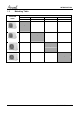
INTRODUCTION 1.8 Matching Table INDOOR UNITS OUTDOOR UNITS AWSI-HGF009-H11 AWSI-HGF012-H11 AWSI-HGF018-H11 AWSI-HGF024-H11 AWSI-HHF009-H11 AWSI-HHF012-H11 AWSI-HHF018-H11 AWSI-HHF024-H11 √ AWAU-YGF009-H11 √ AWAU-YGF012-H11 √ AWAU-YGF018-H11 √ AWAU-YGF022-H11 1-4 SM HGFHHF 1-A.
PRODUCT DATASHEET 2. PRODUCT DATA SHEET HGF009 / HHF009 // YGF009 2.
PRODUCT DATASHEET 2.
PRODUCT DATASHEET 2.
PRODUCT DATASHEET 2.
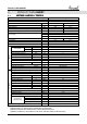
RATING CONDITIONS 3. RATING TING CONDITIONS Rating conditions in accordance with ISO 5151 and ISO 13253 (for ducted units). Cooling: Indoor: 27oC DB 19oC WB Outdoor: 35 oC DB Heating: Indoor: 20oC DB Outdoor: 7oC DB 6oC WB 3.1 Operating Limits R410A Upper limit Lower limit Upper limit Heating Lower limit Cooling Voltage SM HGFHHF 1-A.
OUTLINE DIMENSION OUTLINE NE DIMENSION 4. 4.1 Indoor: HGF/HHF009-012-018-024 Unit: mm Model 09K 12K 18-24K W 730 790 940 SM HGFHHF 1-A.
OUTLINE DIMENSION 4.2 Outdoor: YGF009-012-018-024 Model 09/12 Model 18/24 4-2 SM HGFHHF 1-A.
OUTLINE DIMENSION Unit: mm Model 09-12K 18-24K W 776 913 SM HGFHHF 1-A.
PERFORMANCE DATA & PRESSURE CURVES 5. PERFORMANCE RFORMANCE DATA 5.1 HGF009 / HHF009 // YGF009 5.1.1 Cooling Capacity (kW) Entering Air DB OD Coil(oC) Data 20 25 30 35 40 46 Entering Air WB/DB ID Coil(oC) 15/21 17/24 19/27 21/29 23/32 TC SC 2.69 1.77 2.84 1.87 2.92 1.95 2.99 2.00 3.06 2.04 PI 0.63 0.63 0.64 0.64 0.64 TC SC 2.55 1.73 2.75 1.83 2.89 1.93 2.98 1.99 3.05 2.02 PI 0.68 0.69 0.69 0.70 0.70 TC SC 2.38 1.67 2.59 1.78 2.80 1.89 2.90 1.95 2.99 1.
PERFORMANCE DATA & PRESSURE CURVES 5.1.3 Heating Capacity (kW) ENTERING AIR DB ID COIL(OC) 15 20 25 ENTERING WB OD COIL(oC) TH Pl TH Pl TH Pl -10 1.48 0.62 1.42 0.66 1.36 0.70 -7 1.59 0.64 1.53 0.67 1.48 0.71 -2 1.69 0.65 1.63 0.69 1.58 0.72 2 2.05 0.68 1.97 0.72 1.89 0.76 6 2.90 0.73 2.81 0.78 2.72 0.83 10 3.15 0.77 3.07 0.82 2.98 0.88 15 3.40 0.80 3.32 0.86 3.24 0.92 20 3.59 0.83 3.50 0.90 3.40 0.97 LEGEND TH PI WB DB ID OU 5.1.4 5.1.4.
PERFORMANCE DATA & PRESSURE CURVES 5.1.4.2 Heating Discharge Pressure(Bar[g]) Discharge Pressure VS.Outdoor Temp 38 36 34 32 30 28 26 24 22 20 18 16 25 DB (ºC) 20 DB (ºC) 15 DB (ºC) -10 -5 0 5 o 10 15 20 Outdoor Temp.( WB C ) 5.2 HGF012 / HHF012 // YGF012 5.2.1 Cooling Capacity (kW) Entering Air DB OD Coil(oC) Data 20 25 30 35 40 46 SM HGFHHF 1-A.1 GB Entering Air WB/DB ID Coil(oC) 15/21 17/24 19/27 21/29 23/32 TC 3.29 3.46 3.57 3.66 3.74 SC 2.17 2.28 2.38 2.45 2.
PERFORMANCE DATA & PRESSURE CURVES LEGEND TC SC PI WB DB ID OU 5.2.2 – – – – – – – Total Cooling Capacity, kW Sensible Capacity, kW Power Input, kW Wet Bulb Temp., (oC) Dry Bulb Temp., (oC) Indoor Outdoor Heating Capacity (kW) ENTERING AIR DB ID COIL(OC) 15 20 25 ENTERING WB OD COIL(oC) TH Pl TH Pl TH Pl -10 1.85 0.78 1.78 0.83 1.71 0.87 -7 1.99 0.80 1.92 0.84 1.85 0.89 -2 2.11 0.81 2.04 0.86 1.97 0.90 2 2.57 0.85 2.46 0.90 2.36 0.95 6 3.62 0.91 3.52 0.97 3.
PERFORMANCE DATA & PRESSURE CURVES 5.1.5 5.1.5.1 Curves Cooling Suction Pressure VS.Outdoor Temp Suction Pressure (Bar[g]) 14.0 15/21(WB/DB 17/24(WB/DB 19/27(WB/DB 21/29(WB/DB 23/32(WB/DB 13.0 12.0 ºC) ºC) ºC) ºC) ºC) 11.0 10.0 9.0 8.0 7.0 15 20 25 30 35 40 46 o Outdoor Temp.(DB C ) 5.1.5.2 Heating Discharge Pressure(Bar[g]) Discharge Pressure VS.Outdoor Temp 36 34 32 30 28 26 24 22 20 18 16 25 DB (ºC) 20 DB (ºC) 15 DB (ºC) -10 -5 0 5 o 10 15 20 Outdoor Temp.
PERFORMANCE DATA & PRESSURE CURVES 5.3 HGF018 / HHF018 // YGF018 5.3.1 Cooling Capacity (kW) Entering Air DB OD Coil(oC) Data TC SC PI TC SC PI TC SC PI TC SC PI TC SC PI TC SC PI 20 25 30 35 40 46 Entering Air WB/DB ID Coil(oC) 15/21 5.40 3.56 1.26 5.11 3.47 1.36 4.78 3.36 1.47 4.43 3.20 1.59 4.03 3.01 1.71 3.49 2.77 1.87 17/24 5.70 3.75 1.27 5.52 3.68 1.37 5.21 3.57 1.49 4.80 3.43 1.61 4.38 3.24 1.74 3.82 2.97 1.90 19/27 5.88 3.91 1.27 5.81 3.88 1.38 5.63 3.80 1.51 5.30 3.71 1.64 4.78 3.
PERFORMANCE DATA & PRESSURE CURVES 5.1.3 Heating Capacity (kW) ENTERING AIR DB ID COIL(OC) 15 20 25 ENTERING WB OD COIL(oC) TH Pl TH Pl TH Pl -10 2.99 1.34 2.88 1.42 2.76 1.49 -7 3.22 1.37 3.11 1.44 2.99 1.52 -2 3.42 1.39 3.31 1.47 3.19 1.55 2 4.16 1.45 3.99 1.54 3.82 1.64 6 5.87 1.56 5.70 1.67 5.50 1.77 10 6.38 1.65 6.21 1.76 6.04 1.88 15 6.90 1.72 6.73 1.85 6.56 1.97 20 7.27 1.77 7.10 1.92 6.90 2.07 LEGEND TH PI WB DB ID OU 5.1.6 5.1.6.
PERFORMANCE DATA & PRESSURE CURVES 5.1.6.2 Heating Discharge Pressure(Bar[g]) Discharge Pressure VS.Outdoor Temp 40 38 36 34 32 30 28 26 24 22 20 18 16 25 DB (ºC) 20 DB (ºC) 15 DB (ºC) -10 -5 0 5 o 10 15 20 Outdoor Temp.( WB C ) 5.4 HGF024 / HHF024 // YGF024 5.4.1 Cooling Capacity (kW) Entering Air DB OD Coil(oC) 20 25 30 35 40 46 5-8 Data TC SC PI TC SC PI TC SC PI TC SC PI TC SC PI TC SC PI Entering Air WB/DB ID Coil(oC) 15/21 6.28 4.14 1.46 5.94 4.03 1.58 5.55 3.90 1.70 5.14 3.
PERFORMANCE DATA & PRESSURE CURVES LEGEND TC SC PI WB DB ID OU 5.4.2 – – – – – – – Total Cooling Capacity, kW Sensible Capacity, kW Power Input, kW Wet Bulb Temp., (oC) Dry Bulb Temp., (oC) Indoor Outdoor Heating Capacity (kW) ENTERING AIR DB ID COIL(OC) 15 20 25 ENTERING WB OD COIL(oC) TH Pl TH Pl TH Pl -10 3.41 1.52 3.28 1.62 3.15 1.70 -7 3.67 1.56 3.54 1.64 3.41 1.73 -2 3.90 1.58 3.77 1.67 3.64 1.77 2 4.75 1.65 4.55 1.76 4.36 1.86 6 6.70 1.78 6.50 1.90 6.
PERFORMANCE DATA & PRESSURE CURVES 5.1.7 5.1.7.1 Curves Cooling Suction Pressure VS.Outdoor Temp Suction Pressure (Bar[g]) 14.0 15/21(WB/DB 17/24(WB/DB 19/27(WB/DB 21/29(WB/DB 23/32(WB/DB 13.0 12.0 ºC) ºC) ºC) ºC) ºC) 11.0 10.0 9.0 8.0 7.0 6.0 15 20 25 30 35 40 46 o Outdoor Temp.(DB C ) 5.1.7.2 Heating Discharge Pressure(Bar[g]) Discharge Pressure VS.Outdoor Temp 40 38 36 34 32 30 28 26 24 22 20 18 16 25 DB (ºC) 20 DB (ºC) 15 DB (ºC) -10 -5 0 5 o 10 15 20 Outdoor Temp.
SOUND LEVEL CHARACTERISTICS 6. SOUND LEVEL CHARACTERISTICS 6.1 Sound Pressure Level - Indoor 6.
SOUND LEVEL CHARACTERISTICS HGF012 / HHF012 Cooling HGF012 / HHF012 Heating Noise spectrum & NC Curves Noise spectrum & NC Curves 90 Octave Band Sound Pressure Level [dB re 20 mPa] 80 70 NC65 60 NC60 NC55 50 NC50 NC45 40 NC40 NC35 30 NC30 NC25 20 NC20 NC15 10 Octave Band Sound Pressure Level [dB re 20 mPa] 90 80 70 NC65 NC60 NC55 NC50 NC45 NC40 NC35 NC30 60 50 40 30 NC25 NC20 NC15 20 10 0 0 63 125 250 500 1000 2000 4000 63 8000 Octave Band Center Frequencies [Hz] HGF018 / H
SOUND LEVEL CHARACTERISTICS HGF024 / HHF024 Cooling HGF024 / HHF024 Heating Noise spectrum & NC Curves 90 80 80 70 NC65 NC60 NC55 NC50 NC45 NC40 NC35 NC30 60 50 40 30 NC25 NC20 NC15 20 10 Octave Band Sound Pressure Level [dB re 20 mPa] Octave Band Sound Pressure Level [dB re 20 mPa] Noise spectrum & NC Curves 90 70 NC65 NC60 NC55 NC50 NC45 NC40 NC35 NC30 60 50 40 30 NC25 NC20 NC15 20 10 0 0 63 125 250 500 1000 2000 4000 8000 Octave Band Center Frequencies [Hz] SM HGFHHF 1-A.
SOUND LEVEL CHARACTERISTICS 6.3 Sound Pressure Level - Outdoor 6.
SOUND LEVEL CHARACTERISTICS YGF009 Cooling YGF009 Heating Noise spectrum & NC Curves 90 90 80 80 70 NC65 NC60 NC55 NC50 NC45 NC40 NC35 NC30 60 50 40 30 NC25 NC20 NC15 20 10 Octave Band Sound Pressure Level [dB re 20 mPa] Octave Band Sound Pressure Level [dB re 20 mPa] Noise spectrum & NC Curves 70 NC65 NC60 NC55 NC50 NC45 NC40 NC35 NC30 60 50 40 30 NC25 NC20 NC15 20 10 0 0 63 125 250 63 500 1000 2000 4000 8000 125 250 Octave Band Center Frequencies [Hz] Octave Band Center Frequenci
SOUND LEVEL CHARACTERISTICS YGF018 Cooling YGF018 Heating Noise spectrum & NC Curves 90 80 80 70 NC65 NC60 NC55 NC50 NC45 NC40 NC35 NC30 60 50 40 30 NC25 NC20 NC15 20 10 Octave Band Sound Pressure Level [dB re 20 mPa] Octave Band Sound Pressure Level [dB re 20 mPa] Noise spectrum & NC Curves 90 70 NC65 NC60 NC55 NC50 NC45 NC40 NC35 NC30 60 50 40 30 NC25 NC20 NC15 20 10 0 0 63 125 250 500 63 1000 2000 4000 8000 125 YGF024 Cooling YGF024 Heating Noise spectrum & NC Curves 90 90 80 8
ELECTRICAL DATA 7. ELECTRICAL DATA MODEL YGF009 YGF012 YGF018 YGF024 To indoor Power Supply Max Current, A 5.1A 1PH-220-240V-50Hz 6.3A 11.1A Circuit Breaker, A 10A 16A 11.7 25A 25A Power Supply No. X Cross Section mm2 3x1.0 3x2.5 Interconnecting Cable No. X Cross Section mm2 3X1.0+2X0.75 5x2.5 NOTE Power wiring cord should comply with local laws and electrical regulations requirements. SM HGFHHF 1-A.
WIRING DIAGRAM 8. 8.1 WIRING DIAGRAM HGF009 / HHF009 // YGF009 SM HGFHHF 1-A.
WIRING DIAGRAM 8.2 8-2 HGF012 / HGF012 // YGF012 SM HGFHHF 1-A.
WIRING DIAGRAM 8.3 HGF018 / HHF018 // YGF018 SM HGFHHF 1-A.
WIRING DIAGRAM 8.4 8-4 HGF024 / HHF024 // YGF024 SM HGFHHF 1-A.
REFRIGERATION DIAGRAMS 9. REFRIGERATION DIAGRAMS SM HGFHHF 1-A.
TUBING CONNECTIONS 10. TUBING CONNECTIONS When the outdoor unit is installed above the indoor unit an oil trap is required every 5m along the suction line at the lowest point of the riser. In case the indoor unit is installed above the outdoor, no trap is required. SM HGFHHF 1-A.
CONTROL SYSTEM 11. CONTROL SYSTEM 11.1 Electronic Control 11.1.1 Abbreviations AC A/C ANY COMP CPU E2PROM, EEP H/W ICT IF, IFAN IR Max Min min NA OCT OF, OFAN RAT RC R/C RCT RH RV SB, STBY Sec Sect SH SPT ST S/W TEMP W/O SM HGFHHF 1-A.
CONTROL SYSTEM 11.1.2 System Operation Concept 11.1.3 Compressor operation For each Mode including POWER OFF & SB, a Min time delay of 3 min before COMP restarting except during outdoor deicing. Whenever COMP starts, it will not stop in 6 min even the RAT is changed. * For the units with memory function, the 1st time of Power ON, there will be no 3 min delay if the previous stage of unit is OFF. 11.1.4 Indoor Fan Control 8 Indoor fan speeds are determined for each model.
CONTROL SYSTEM 11.1.5.1 OFAN Speed Type The OFAN motor is a one speed AC motor and controlled by the relay on outdoor controller. 11.1.5.2 General rules 1. The OFAN is ON when COMP ON during Cool, Dry and Heat Mode. 2. When the unit is off by remote control, in safety stops and stop after reaching to the temperature point, the outdoor fan stops. 3. Outdoor fan OFF will compressor when COMP is OFF during cooling and heating mode. 11.1.6 Refrigerant control Capillary is used in each mode. 11.1.
CONTROL SYSTEM IFAN speed depends on the indoor coil temperature Anti-cold air function When starting the heating mode, anti-cold air function will be activated and IFAN can run at low speed or stop running. This function will terminate after the unit runs for 2min or the ICT reaches 40 degree. Residual heat blowing function During heating, when the stopping condition for the COMP is reached, the COMP and OFAN stop running while the louver moves to position L.
CONTROL SYSTEM off, the air deflector will stay in position 0. The swing is available only when the swing function is set and the indoor fan is running. The louver swing can also be set between L and B, between A and C, between B and D. 11.8 Protections 11.8.1 Indoor Coil Defrost Protection During Cool Mode/Dry Mode, this protection prevents freezing of the indoor heat exchanger. When ICT <= 0 C for continuous 3 mins, COMP and OFAN will stop and IFAN will run at its setting speeds.
CONTROL SYSTEM The minimum operating time of heating mode before deicing: a) 40 min after 1st time of power on b) 5 min after system is STBY by RC or temperature condition. 11.8.4.2 Deicing Protection Procedure 1. Start to defrost: COMP stops and starts up 55S later 2. Start to defrost: Outdoor fan will stop after COMP stops for 50S. 3. Defrosting finish: COMP stops and starts up 55S later. 4. Defrosting finish: Outdoor fan will start up when the COMP is stopping. 11.8.4.
CONTROL SYSTEM 11.10 Characteristics of sensor 11.10.1 RAT/OAT RAT/OAT R-T chart 140 130 120 110 Resistance(Kohm) 100 90 80 70 60 50 40 30 20 10 0 -20 -15 -10 -5 0 5 10 15 20 25 30 35 40 45 50 55 60 65 70 35 40 45 50 55 60 65 70 Temperature(C) 11.10.2 ICT/OCT ICT/OCT R-T Chart 180 170 160 150 140 Resistance(Kohm) 130 120 110 100 90 80 70 60 50 40 30 20 10 0 -20 -15 -10 -5 0 5 10 15 20 25 30 Temperature(C) SM HGFHHF 1-A.
CONTROL SYSTEM 11.10.3 CTT CTT R-T Chart 150 140 130 120 110 Resistance(Kohm) 100 90 80 70 60 50 40 30 20 10 0 0 5 10 15 20 25 30 35 40 45 50 55 60 65 70 75 80 85 90 Temperature(C) 11-8 SM HGFHHF 1-A.
TROUBLESHOOTING 12. TROUBLESHOOTING 12.1 ELECTRICAL & CONTROL TROUBLESHOOTING 12.1.1 Precautions before Performing Inspection or Repair Be cautious during installation and maintenance. Do operation following the regulations to avoid electric shock and casualty or even death due to drop from high attitude. * Static maintenance is the maintenance during de-energization of the air conditioner. For static maintenance, make sure that the unit is de-energized and the plug is disconnected.
TROUBLESHOOTING 12.1.3 Judgment by Indoor/Outdoor Unit Diagnostics If the malfunction still exists 4min later after stop of unit due to compressor protection, error code will be directly displayed though indoor display. In other situations, error code can be displayed by pressing LIGHT button 6 times within 4s. 2* 7 segments Fault description LEDs blinking (0.5s ON and 0.
EXPLODED VIEW & SPARE PART LIST 13. EXPLODED VIEW & SPARE PART LIST 13.1 Exploded view of indoor unit: HGF009/HHF009 SM HGFHHF 1-A.
EXPLODED VIEW & SPARE PART LIST 13.2 NO.
EXPLODED VIEW & SPARE PART LIST 13.3 NO.
EXPLODED VIEW & SPARE PART LIST 13.4 13-4 Exploded view of indoor unit: HGF012/HHF012 SM HGFHHF 1-A.
EXPLODED VIEW & SPARE PART LIST 13.5 NO.
EXPLODED VIEW & SPARE PART LIST 13.6 NO.
EXPLODED VIEW & SPARE PART LIST 13.7 Exploded view of indoor unit: HGF018 SM HGFHHF 1-A.
EXPLODED VIEW & SPARE PART LIST 13.8 NO.
EXPLODED VIEW & SPARE PART LIST 13.9 Exploded view of indoor unit: HHF018, HHF024 SM HGFHHF 1-A.
EXPLODED VIEW & SPARE PART LIST 13.10 NO.
EXPLODED VIEW & SPARE PART LIST 13.11 NO.
EXPLODED VIEW & SPARE PART LIST 13.12 13-12 Exploded view of indoor unit: HGF024 SM HGFHHF 1-A.
EXPLODED VIEW & SPARE PART LIST 13.13 NO.
EXPLODED VIEW & SPARE PART LIST 13.14 13-14 Exploded view of outdoor unit: YGF009,YGF012 SM HGFHHF 1-A.
EXPLODED VIEW & SPARE PART LIST 13.15 NO. 1 2 3 4 5 6 7 8 9 10 11 12 13 14 15 16 17 18 19 20 21 22 23 24 Spare part list of outdoor Unit: YGF009 Part Code 22413007 01533029P 26233100 01203799P 01233066 10333427 150130671 0111347201 01703052 01253031 1112320501 0306301701 02603240 42010265 33010026 01303183 26233433 0170308901P 07100003 07100005 40040007_GY1 33000018 00103203 0312328601 0130304802 430004022 430004002 06123401 00183012 76710217 SM HGFHHF 1-A.
EXPLODED VIEW & SPARE PART LIST 13.16 NO.
EXPLODED VIEW & SPARE PART LIST 13.17 Exploded view of outdoor unit: YGF018 SM HGFHHF 1-A.
EXPLODED VIEW & SPARE PART LIST 13.18 NO.
EXPLODED VIEW & SPARE PART LIST 13.19 Exploded view of outdoor unit: YGF024 SM HGFHHF 1-A.
EXPLODED VIEW & SPARE PART LIST 13.20 Spare part list of outdoor Unit: YGF024 NO.
APPENDIX 14. APPEDDIX APPENDIX SM HGFHHF 1-A.