PROTECT YOUR WARRANTY This unit must be installed by a registered, licensed installer as required by Government regulations.
Contents 2 Important Safety Instructions 3 Product Overview 5 Selecting the Installation Place 6 Installation 8 Technical Specifications 19 After Sales Support 1300 886 649 | info@tempo.
Important Safety Instructions PROTECT YOUR WARRANTY These installation instructions are for use by an appropriately qualified installer. Do not try to install the air conditioner on your own; doing so will expose you to danger and void the warranty. Contact a licensed installer. FOR THE INSTALLER Read this guide before installation. The appliance must be installed by a professional installer according to the instructions in this manual and in accordance with all applicable regulations.
Important Safety Instructions (Cont.) Installation • The air conditioner’s outdoor unit must be installed on suitably strong supports. • During installation of the indoor and outdoor units, do not allow children access to the working area. • Make sure that the base of the outdoor unit is firmly fixed, otherwise it will produce abnormal noise and vibration during use.
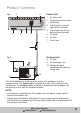
Product Overview 1 Fig. 1 2 Indoor Unit 1 2 3 d 3 4 5 6 4 5 6 7 Air return grid Operational performance indications Adjustment fin for left/ right airflow direction Adjustment flap for up/ down airflow direction Air outlet Air filter Drain tube 7 Outdoor Unit Fig. 2 8 Air inlet 9 Air discharge vent 10 Refrigerant pipe connection and electric wiring cord 8 9 10 This Air Conditioner is made up of an indoor unit, outdoor unit and a remote control.
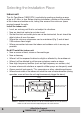
Selecting the Installation Place Indoor unit This Air Conditioner (18000 BTU) is suitable for cooling or heating a room of up to 41-46m2 in size. Before starting installation, decide on the position of the indoor and outdoor units, taking into account the minimum space required around the units.
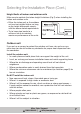
Selecting the Installation Place (Cont.) Height limits of indoor and outdoor units Make sure to maintain the below height limitations (Fig.2) when installing the indoor and outdoor units. • Either the indoor unit or the outdoor unit can be installed higher, as long as the height differences comply with the above stated requirements. • Try to keep pipe bends to a minimum so as to maintain Fig.2 maximum performance of the units.
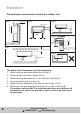
Installation Detailed space requirements around the outdoor unit Fig.4 Fig.5 500mm(1'8") min 100mm(4") min 200mm(8") min 500mm(1'8") min Fig.3 500mm(1'8") min Fig.6 200mm(8") min 300mm(1') min 200mm (8")min Fig.7 500mm (1'8")min Space for maintenance 100mm(4") min Fig.8 1000mm(3'4") min The above listed clearances must be maintained: 1. When there are obstacles above the unit (Fig.3). 2. When the front (air outlet) is open (Fig.4). 3.
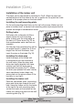
Installation (Cont.) Installation of the indoor unit The pipes can be connected as illustrated in Fig.9. When the pipes are connected to exit at the sides of the unit, a groove for the pipes has to be opened at the proper place on the base stand. Installing the wall-mounting plate Fix the wall-mounting plate firmly on the wall with screws. Make sure the plate is installed level, a slanted wall-mounting plate might jeopardise the smooth discharge of condensation water. Fig.
Installation (Cont.) Inspections • Check if the hooks at the top and bottom are firmly fixed. • Check if the position of the master unit is properly levelled. • The drain pipe should not curve upward (Fig.13). • The drain pipe should be at the lower part of the wall pipes (Fig.13). Fig.13 Connecting pipe Connecting wires Wall pipe Drain pipe Drain pipe Installation of the outdoor unit • Try to ship the product to the installation location in its original package.
Installation (Cont.) Pipe connection and air purging * * The following pipe connection and air purging instructions are only suitable for air conditioner models other than quick coupler models. Instructions for quick coupler models follow on page 13. The air conditioning system must be installed in way that ensures that no dust, foreign articles, air or moisture can enter the system. Pay particular attention when connecting the pipes for the outdoor unit.
Installation (Cont.) Air purging with a vacuum pump After having connected the indoor and outdoor units, make sure all pipes have been properly connected, then bleed the air and humidity from the refrigerant circuit by following the below steps. 1. Remove the charging port cap and connect the manifold gauge and the vacuum pump to the charging valve by service hoses, as illustrated (Fig.15). 2. Open the valve of the low pressure side of the manifold gauge, then run the vacuum pump.
Installation (Cont.) Gas leakage inspection After the pipeline connection is done, use a leakage inspection device or soap suds to carefully check if there is any leakage at the joints. This is an important step to ensure the quality of installation. Once a leakage is detected, proper treatment should be taken immediately. Pipe connection for split type quick coupler models If you have purchased the air conditioner for split type quick coupler models, follow the below pipe connection instructions.
Installation (Cont.) Pipelines connection for whole unit type quick coupler models 14 After Sales Support 1300 886 649 | info@tempo.org Wrap with ethylene tapes Fig.18 (This section does not apply to the AK18000-RC Air Conditioner.) 1. Remove the two screws on the maintenance plate with a screwdriver and take off the plate, then remove the dust caps on both the indoor male coupler and outdoor female coupler (Fig.18). 2. To open the inner hooks, apply a little Fig.
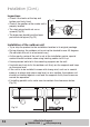
Installation (Cont.) Connection of the power cable 1. Remove the drawer of the outdoor unit. 2. Non-quick coupler: Connect the indoor power and control wires with the matching outdoor wires in accordance with the electric schematic diagram and make sure that the connection is firmly done (Fig.24) Quick coupler: Directly connect the indoor and outdoor quick cable couplers after disassembling the outdoor unit’s connecting box cover (Fig.25). 3.
Installation (Cont.) Installation checklist • Check and ensure that the installation place is solid and strong enough to support the weight of the unit. • Check and ensure that condensation water can easily drain away. • Check and ensure that in the vicinity of the unit: XX There is nothing that prevents ventilation or obstructs operation in front of the unit. XX There is suitable protection for the outdoor unit in case of direct exposure to sea breezes.
Installation (Cont.) Troubleshooting guide This air conditioner is equipped with a self-diagnosis function to help you identify potential problems. Should you encounter problems with your air conditioner, contact our after sales support centre using the details on the bottom of the page. However, before calling for service, consult the selfdiagnosis information below.
Installation (Cont.) Quick connector installation instruction* * Only relevant for the installation of stainless quick connector pipes -- this section does not apply to the AK-18000-RC Air Conditioner • To expand the connecting pipe, hold one side then expand it following the right direction. • Make sure the angles have a radian at some extent while installing the stainless soft pipe. Angels need to be around, not bent (to the quick connecting spot and drilled point in the wall).
Technical Specifications AK-18000-RC Heating AK-18000-RC 220-240V, 50Hz Rated Voltage & Frequency Cooling AK-12000-RC Capacity 2600W (1600-3000W) 3500W (2200-4000W) 5100W (2800-5500W Power Input 675W (420-1160W) 910W (600-1400W) 1504W (720-1880W) Current Input 3.4A (1.9-5.4A) 4.2A 2.6-6.5A) 7.0A (3.2-8.5A) EER 3.85w/w 3.85w/w 3.
Technical Specifications (Cont.) Indoor Evaporator Outdoor Fan Motor Outdoor Condenser AK-18000-RC AK-12000-RC AK-18000-RC Rows/Tubes/ Circuits 2/15/2 2/17 2/20 Tube Pitch/ Row Pitch/Fin Spacing 21/12.7/1.4mm 21/12.7/1.6mm 21/12.7/1.6/1.7mm Fin Type Open Window Open Window Hydrophilic Aluminium Foil Tube Outside Ø & Type Ø7 Internal Thread Tube Ø7 Internal Thread Tube Ø7/R410A Coil LxHxW 615 x 315 x 25.4mm 705 x 402 x 25.4mm 705 x 326 x 25.
Technical Specifications (Cont.) Refrigerant Piping / Connection wiring AK-18000-RC AK-12000-RC AK-18000-RC Liquid Side/ Gas Side/ Length Ø6.0 + Ø9.52 x 3500mm Ø6.0 + Ø9.52 x 5000mm Ø6.0 + Ø12.0 x 5000mm Max. Refrigerant Pipe Length / Max. Difference in Level 15 / 5m 15 / 5m 15 / 5m Power Cord (Number x Diameter x Length) 3 x 1.5mm2 x 2m 3 x 1.5mm2 x 2m 3 x 2.5mm2 x 2.68m Indoor & Outdoor Connecting Cable (Number x Diameter x Length) 4 x 1.5mm2 x 6080mm 4 x 1.5mm2 x 6080mm 4 x 1.
After Sales Support 1300 886 649 | info@tempo.
After Sales Support 1300 886 649 | info@tempo.
Licensed Installer Details Please fill in the details below: Name of licensed installer: ....................................................................... License number: ....................................................................... Date of installation: ....................................................................... Signature: ....................................................................... After Sales Support 1300 886 649 | info@tempo.