
Operation Manual

6
After Sales Support
1300 886 649 | info@tempo.org
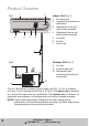
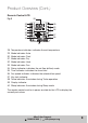
Indoor Unit (Fig. 1)
1 Air return grid
2 Operational performance
indications
3 Adjustment fin for left/
right airflow direction
4 Adjustment flap for up/
down airflow direction
5 Air outlet
6 Air filter
7 Drain tube
Outdoor Unit (Fig. 2)
8 Air inlet
9 Air discharge vent
10 Refrigerant pipe
connection and electric
wiring cord
This Air Conditioner is made up of an indoor unit (Fig. 1 & Fig. 3), outdoor
unit (Fig. 2) and a remote control (Fig. 4 & Fig. 5). The indoor unit is installed
on a wall of the room to be air conditioned. The outdoor unit is installed in a
protected area outdoors, on the ground or on a wall on suitable brackets.
NOTE: Figures and descriptions throughout this user manual are for
explanatory and illustrative purposes only and may differ slightly from
the appearance of the product purchased.
Product Overview
d
1 2
3 4 5 6
7
8
9
10
Fig. 1
Fig. 2