Air Conditioner Service Manual Downloaded from AC-Manual.
Model Gr oup: AC-S10 Model : AC-S10CK AC-S10HK Model No: AC-S10CK_S10HK Version 1.0 Downloaded from AC-Manual.
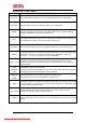
Content Feature …………………………………..………………………………………………..4 Specifications ……………………………………………………………………………. 5 Operating range …………………………………………………………………………. 5 Remote control …………………………………………………………………………...7 Refrigeration cycle ……………………………………………………………………….10 Operation details …………………………………………………………………………12 Installation ……………………………………………………………………………….. 22 2-way, 3-way valve ……………………………………………………………………… 33 Trouble shooting ………………………………………………………………………… 41 Exploded drawing …………………………………………………………………… ….
CHAPTER 1: FEATURES MODE DESCRIPTION COOLING Cools, dehumidifies and filters the room air. Maintains desired room temperature. HEATING Heats and filters the room air. Maintains desired room temperature. SMART DRY FAN ONLY SLEEP AUTO Operates the appliance at COOLING, HEATING or DRY mode, maintaining desired temperature dependent upon the room temperature. Dehumidifies and softly cools the room air.
CHAPTER 2: SPECIFICATIONS (SEE APPENDIX A) CHAPTER 3: OPERATING RANGE 1. TEMPERATURE RANGE FOR T1 CLIMATE AIR CONDITIONER l The preset temperature of the appliance ranges from 18oC to 32oC. l The ambient temperature of the cooling only air conditioner ranges from 18oC to 43oC. l The ambient temperature of the heat pump ranges from –7oC to 43oC. l The rated cooling operation test condition is as following.
3. REFRIGERANT PIPING l The maximum length of the connecting refrigerant piping between indoor unit and outdoor unit is 15m and the maximum elevation difference between indoor and outdoor units are 5m. l If the refrigerant piping is longer than 7m,additional refrigerant charge 20g/m for below 1/2 inch gas pipe and 30g/m for below 5/8 or 3/4 inch gas pipe is advisable.
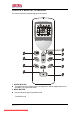
CHAPTER 4: REMOTE CONTROLLER The remote controller transmits signals to the system. 4 9 6 5 2 3 7 8 1 1. ON/OFF BUTTON l The appliance will be started when it is energized or will be stopped when it is in operation, if you press this button. 2. MODE BUTTON l Used to select the type of operation mode. COOLING mode Model No: AC-S10CK_S10HK Version 1.0 Downloaded from AC-Manual.
DRY mode FAN ONLY mode HEATING mode 3. FAN SPEED BUTTON l Used to select the indoor fan motor speed. Automatic fan speed High fan speed Medium fan speed Low fan speed 4.TEMPERATURE SETTING BUTTON l Used to adjust the preset room temperature. l Used to adjust time in TIMER mode. 5. SWING BUTTON l Press to adjust airflow direction. 6. SMART BUTTON l Used to enter fuzzy logic operation directly, regardless of the unit is on or off. 7.
Indication symbols on LCD: Signal transmit. Super indicator Smart indicator Sleep indicator Cooling indicator Dry indicator Fan only indicator Heating indicator Model No: AC-S10CK_S10HK Version 1.0 Downloaded from AC-Manual.
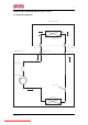
CHAPTER 5: REFRIGERATION CYCLE 1. Cooling only appliance I ndoor uni t ÆÀ Ö ä Ï µ Í ³ Í ¼ evaporator l i quid side gas si de Outdoor uni t 3-way val v e 2-way val v e accum ul ator com pressor capi l l a r y condenser Model No: AC-S10CK_S10HK Version 1.0 Downloaded from AC-Manual.
2. Heat pump I ndoor uni t ¼Ê õ ²Î Ê ý : evaporator l i quid side gas si de Outdoor uni t 3-way valve 2-way valve check valve accum ul ator com pressor reverse valve capi l l a r y condenser defrost heating cooling Flow of refrigerant Model No: AC-S10CK_S10HK Version 1.0 Downloaded from AC-Manual.
CHAPTER 6: OPERATION DETAILS 1. SAFETY CONTROL l 3 minutes delay for compressor The compressor is ceased for 3 minutes to balance the pressure in the refrigeration cycle in order to protect the compressor. l 59 seconds delay for reversing valve The 4-way reversing valve delay for 59 seconds to prevent the refrigerant abnormal noise when the HEATING operation is OFF or switched to other operation modes.
2. AIR FLOW DIRECTION CONTROL l This function is to swing the louver up and down automatically and to set it at a desired position. l The procedure is as following. F Press the ON/OFF button to operate the appliance. The louver will swing automatically to the default position. F Press the SWING button to swing the louver up and down automatically. F Repress the SWING button to stop the louver at a desired position. l The louver is controlled by a step motor.
ROOM TEMP. SET TEMP. +1¡æ ( COMP. O N ) SET TEMP. - 1¡æ ( COMP. OFF) I ndoor fan m otor speed Compressor Outdoor fan m otor set speed ON ON More than More than 3 mins 3 mins set l ow speed set speed set l ow set speed speed OFF ON OFF ON OFF ON OFF ON 4. DRY MODE OPERATION l The appliance starts as COOLING operation. If 3 minutes elapses after starting, the appliance will sense the intake air temperature and minus 1.5o C as the setting temperature.
tion diagram is shown as following. More than o Set Temp +11 3 mins SET TEMP. +4o. 5¡æ (Comp Off) ( CO MP. OFF) B B A A SET TEMP. +o2. 5¡æ Set Temp -1 COMP. (Comp(On) ON) 30 secs 30 secs ROOM TEMP. I ndoor fan m otor speed Compressor Outdoor fan m otor * set speed UL * OFF * set speed UL ON OFF ON OFF ON OFF ON OFF * OFF * The indoor fan motor is controlled by Cold Air Preventive System. l The indoor fan motor is controlled by Cold Air Preventive System. 6.
l The indoor fan motor speed will be controlled as following. (for 24K heat pump) 7. SMART MODE OPERATION l When SMART air conditioning is selected, the operation mode and preset temperature are set automatically according to the room temperature at starting operation. l The operation procedure of cooling only is as following. Intake air temperature at operation start Preset temperature Over 26o C Below 26o C 26o C Operation mode COOLING Intake air temperature minus 1.
Intake air temperature at operation start Preset temperature Over 26oC 21oC ~ 26oC Below 21oC 26oC 22oC Operation mode COOLING Intake air temperature at operation start DRY HEATING The initial mode will be continued and independent upon the room temperature changing. l If initial mode is selected, that mode is continued, independent upon the temperature changing. l The indoor fan motor speed is automatically determined by Auto Fan Speed.
l The operation procedure of HEATING is as following. Intake air temp. Set tem p. Set tem p.-1¡æ Set tem p.-2¡æ Set tem p.-3¡æ Intake air temp. I ndoor fan m otor speed High Medi um I ndoor fan Low Indoor pipe temperature rises m otor speed Low Medi um Indoor pipe temperature falls 9. INDOOR FAN SPEED CONTROL l Auto Fan Speed control When set to Auto Fan Speed, the indoor fan motor speed is controlled by the difference between the intake air temperature and the preset temperature.
10. EMERGENT START l If you lose the remote controller or it is out of work, you can also operate the appliance by pressing the EMERGENT BUTTON on the indoor unit for an emergent start. l The operation mode is SMART if an emergent start is presented when the appliance is connected to the power at first time. If the appliance is in stand by, the operation mode will restore the last time setting when you press the EMERGENT BUTTON. 11.
Preventive System. l The HEATING and defrosting operation is alternated as following. Switch O N Heating Heating Heating M in 50 m i ns M in 50 m i ns M in 50 m i ns Defrosting Max 10 m i ns l The defrosting procedure is shown as following. Model No: AC-S10CK_S10HK Version 1.0 Downloaded from AC-Manual.
13. TIMER MODE OPERATION l The setting time ranges from 0.5 hour to 24 hours. l OFF-TIMER can be set when the appliance is in operation, and it will be switched OFF when the preset time is achieved. l ON-TIMER can be set when the appliance is in suspension, and it will be switched ON when the preset time is achieved. l Pressing TIMER button once, the last setting time display on the LCD of remote controller. You can adjust the setting time by pressing the TEMPERATURE SETTING BUTTON.
stop in 8 hours. The operation diagram is as following. Max 8 hours 1 hour 1¡æ 2¡æ 2 hours 3¡æ 3 hours Sleep start Sleep stop CHAPTER 7: INSTALLATION Notice: There is detailed information about installation in the OPERATING AND INSTALLATION INSTRUCTIONS MANUAL. The same information is not repeated in this TECHNICIAN SERVICE MANUAL. 1. SELECT THE BEST LOCATION l Indoor unit F There should not be any heat source or steam near the unit.
2. DRILL THE PIPING HOLE WITH 70mm DIAMETER HOLE-CORE DRILL l Line according to the arrows marked on the lower left and right side of the installation plate. l The meeting point of the extended line is the center of the hole. l Drill the piping hole at either the right or the left and the hole should be slightly slant to the outdoor side. 3. PIPING AND DRAINAGE OF INDOOR UNIT l Preparation of piping 1) Cut the pipes and the cable F Use the accessory piping kit or the pipes purchased locally.
F Cut the cable a 1.5m longer than the pipe length. Model No: AC-S10CK_S10HK Version 1.0 Downloaded from AC-Manual.
2) Remove burrs F Remove burrs from cut edges of pipes. F Turn the pipe end down to avoid the metal powder entering the pipe. F Caution: If the burrs are not removed, they may cause a gas leakage. Model No: AC -S10CK_S10HK Version 1.0 Downloaded from AC-Manual.
3) Flaring the pipes F Insert the flare nuts, mounted on the connection ports of both indoor and outdoor units, onto the copper pipes. Some refrigerant gas may leak, when the flare nuts are removed from the indoor unit, as some gas is charged to prevent the inside of the pipe from rusting. F Fit the copper pipe end into the bar of flare tool about 0~0.5mm higher . F Flare the pipe ends. 4) Tape the flaring portion to protect it from the dust or damages.
Pipe Size Liquid Side(φ6 or 1/4 inch) Liquid Side (φ10 or 3/8 inch) Liquid Side(φ12 or 1/2 inch) Gas Side (φ10 or 3/8 inch) Gas Side(φ12 or 1/2 inch) Gas Side(φ16 or 5/8 inch) Gas Side(φ19 or 3/4 inch) l Torque 1.8 kg.m 3.5 kg.m 5.5 kg.m 3.5 kg.m 5.5 kg.m 7.5 kg.m 10.0 kg.m Wrap the insulation material around the connecting portion. 4.
F When tightening the flare nut with torque wrench, ensure the direction for tightening follows the arrows on the wrench. Pipe Size Liquid Side(φ6 or 1/4 inch) Liquid Side (φ10 or 3/8 inch) Liquid Side(φ12 or 1/2 inch) Gas Side (φ10 or 3/8 inch) Gas Side(φ12 or 1/2 inch) Gas Side(φ16 or 5/8 inch) Gas Side(φ19 or 3/4 inch) l Torque 1.8 kg.m 3.5 kg.m 5.5 kg.m 3.5 kg.m 5.5 kg.m 7.5 kg.m 10.0 kg.m Connecting the cable to the outdoor unit as shown in OPERATING AND INSTALLATION INSTRUCTIONS MANUAL.
5. CHECKING THE DRAINAGE AND CONNECTING THE CABLE TO INDOOR UNIT l Checking the drainage 1) Remove the grille from the cabinet F Set the up-and-down air direction louver to open position(horizontally) by finger pressure. F Remove the screw caps and the securing screws. F To remove the grille, pull the lower left and right side of the grille toward you (slightly titled) and lift it straight upward(Two tabs on the top inside edge of the grille are clear of their slots).
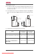
F If you may connect an additional drainage hose, the end of the drainage-outlet should keep distance from the ground.(Do not dip it into water, and fix it on the wall to avoid swinging in the wind.) l In case of the outdoor unit is installed below position of the indoor unit. F Tape the piping, drainage hose and connecting cable from down to up. F Form the piping gathered by taping along the exterior wall and fix it onto the wall by saddle or equivalent. Model No: AC-S7CK_S7HK Version 1.
l In case of the outdoor unit is installed upper position of the indoor unit. F Tape the piping and connecting cable from down to up. F Form the piping gathered by taping along the exterior wall and the trap is required to prevent water from entering into the room. F Fix the piping onto the wall by saddle or equivalent. l Connecting the cable to the indoor unit as shown in the OPERATING AND INSTALLATION INSTRUCTIONS MANUAL. 6.
l Leakage checking F Check a gas-leakage of the connection portion of the piping. F If there is no leakage found, open 2-way again, turn the valve spindle counter-clockwise until it stops. F If there is leakage found, re-tighten the connecting portion with wrench. If the leakage persists, locate a leakage and repair it until leakage ceases.
l Set the both 2-way and 3-way valves to open position with the hexagonal wrench for the unit operation. l Checking a gas leakage for the left piping F connect the manifold gauge to the service port of 3-way valve. Measure the pressure. F Keep it for 5~10 minutes. Ensure if the pressure indicated on the gauge is as same as that of measured at the first time. l Follow the result of right side piping. l The additional gas for air purging has been charged in the outdoor unit.
CHAPTER 8: 2-WAY, 3-WAY VALVE Works Shipping Air purging (Installation) Operation 2-way Valve(Liquid Side) Spindle position Closed (with valve cap) Open (counter-clockwise) Open (with valve cap) Pumping down (Transferring) Closed (clockwise) Evacuation (Servicing) Open Gas charging (Servicing) Open Pressure check (Servicing) Open Gas releasing (Servicing) Open Model No: AC-S10CK_S10HK Version 1.0 Downloaded from AC-Manual.
1. AIR PURGING (INSTALLATION) l Required tools: hexagonal wrench, adjustable wrench, torque wrenches, wrench to hold the joints, and gas leak detector. l The additional gas for air purging has been charged in the outdoor unit. However, if the flare connections have not been done correctly and gas leaks, a gas cylinder and the charge set will be needed. l The air in the indoor unit and in the piping must be purged.
F Check the flare connections for refrigerant gas leakage. F Purge the air from the system. Set the 2-way valve to the open position and remove the cap from the 3-way valve’s service port. Using the hexagonal wrench to press the valve core pin, discharge for three seconds and then wait for one minute. Repeat this three times. F Use torque wrench to tighten the service port cap to a torque of 1.8kg.cm. F Set the 3-way valve to the back seat. F Mount the valve caps to the 2-way and 3-way valves.
l Confirm that both the 2-way and 3-way valves are set to the open position. F Remove the valve caps and confirm that the valve spindles are in the open position. F Be sure to use a hexagonal wrench to operate the valve spindle. l Operate the unit for 10~15 minutes. l Stop operation and wait for 3 minutes, then connect the charge set to the service port of the3-way valve. F Connect the charge hose with the push pin to the service port.
closing it for 1 minute. Repeat 3 times. F After purging the air, use a torque wrench to tighten the flare nut on the 2-way valve. l Check the flare connections for gas leakage. l Disconnect the charge set and the gas cylinder, and set the 2-way and 3-way valves to the open position. F Be sure to use a hexagonal wrench to operate the valve spindles. l Mount the valve caps and the service port cap. F Use torque wrench to tighten the service port cap to a torque of 1.8kg.m.
F Leave the valve on the charge set closed. F Connect the charge hose with the push pin to the service port. l Open the valve (Low side)on the charge set and discharged the refrigerant until the gauge indicates 0kg/cm2.g. F If there is no air in the refrigerant cycle (the pressure when the air conditioner is not running is higher than 1 kg/cm2.g),discharge the refrigerant until the gauge indicates 0.5 to 1 kg/cm 2.g.If this is the case, it will not be necessary to apply an evacuation.
l Close the valve (Low side) on the charge set, turn off the vacuum pump, and confirm that the gauge needle does not move (approximately 5 minutes after turning off the vacuum pump). l Disconnect the charge hose from the vacuum pump. F If the vacuum pump oil becomes dirty or depleted, replenish as needed. 6. GAS CHARGING (AFTER EVACUATION) l Connect the charge hose to the charging cylinder.
refrigerant. F If the system can not be charged with the specified amount of refrigerant, it can be charged with a little at a time (approximately 150g each time) while operating the air conditioner in the cooling cycle. However, one time is not sufficient, wait approximately 1 minute and then repeat the procedure (pumping down pin). F This is different from previous procedures.
CHAPTER 9: TROUBLESHOOTING 1. REFRIGERATION CYCLE SYSTEM l In order to diagnose malfunctions, make sure that there is no electrical problems before inspecting the refrigeration cycle. Such problems include insufficient thermal insulation, problem with the power supply, malfunction of a compressor and indoor or outdoor fan motor. l The normal indoor outlet air temperature and pressure of the refrigeration cycle depends upon various conditions.
2. RELATION BETWEEN THE CONDITION OF THE AIR CONDITIONER AND PRESSURE AND ELECTRIC CURRENT IN COOLING OPERATION l Carry out the measurements of pressure, electric current and temperature fifteen minutes after an operation is started.
4. TROUBLE SUSPENSION TABLE SYMPTON The RUN indicator (green)does not light up The indoor fan does not function correctly The outdoor fan does not function correctly The compressor does not start up Model No: AC-S10CK_S10HK Version 1.0 Downloaded from AC-Manual.com Manuals PROBABLE CAUSE CORRECTIVE ACTION The power source voltage is lower than 198V Repair the power supply No voltage Repair general wiring Correct voltage Replace control P.C.B or display P.C.
SYMPTON The refrigeration system does not function correctly No cooling or heating, only indoor fan operates No cooling or heating, indoor and outdoor fan operate Water accumulates and overflows from indoor unit The air conditioner does not function at all with remote controller or AUX switch button on the indoor unit PROBABLE CAUSE CORRECTIVE ACTION Check for leakage or restriction with ammeter, pressure gauge or surface thermometer Repair refrigeration system and charge refrigerant if necessary
The machine does not function at all with remote controller and EMERGENCY button on the indoor unit. Correct power supply between “L” and “N” of terminal board? None of the three LEDs is ON Yes Measure the secondary voltage of transformer Is the connecting cord correctly connected? Is the measured value approx. 17.0 V AC? Correct the connecting cord correctly Yes Replace the control P.C.B. with a new one. Is the fuse down? Replace the transformer with a new one.
The machine does not function with the remote controller. Push the ON/OFF button on the wireless remote controller. NO NO Are batteries of remote controller proper? Is transmitting signal of the remote controller active? YES Replace the wireless remote controller. YES Does beep sound from the indoor unit? NO YES Replace the batteries with new ones. Is indicator lamp of indoor unit proper? Does connector of display P.C.B.
The room is not cooled at all or not cooled enough in cooling operation. The room is not heated at all or not heated enough in heating operation. The compressor does not operate. Push the buttons EMERGENCY on the indoor unit. Refer to Trouble Suspension Table Measure the resistances of room temperature and indoor pipe temperature thermisters. Some of the three indicator LEDs are lit. Measure the secondary voltage of transformer. Is the measured value approximately 17.
CHAPTER 10: EXPLODED DRAWINGS 1. Exploded view of indoor unit for model: AC -S10CK, AC -S10HK Model No: AC-S10CK_S10HK Version 1.0 Downloaded from AC-Manual.
2. Exploded view of outdoor unit for model: AC -S10CK Model No: AC-S10CK_S10HK Version 1.0 Downloaded from AC-Manual.
3. Exploded view of outdoor unit for model: AC -S10HK Model No: AC-S10CK_S10HK Version 1.0 Downloaded from AC-Manual.
CHAPTER 11: PART LIST 1. Part List of Indoor Unit for AC-S10CK No.
3. Part List of Indoor Unit for AC-S10HK No.
5 54 5. Part List of Outdoor Unit for AC-S10CK No. 1 2 3 4 5 6 7 8 DESCRIPTION Top Cover Condenser Motor Stay Bracket Outdoor Fan Motor Outdoor Fan Cabinet Fan Guard Back Lattice Plate Part No.
6. Part List of Outdoor Unit for AC-S10HK No. 1 2 3 4 5 6 7 8 DESCRIPTION Top Cover Condenser Motor Stay Bracket Outdoor Fan Motor Outdoor Fan Cabinet Fan Guard Back Lattice Plate Part No.
APPENDIX A Description Singapore / AKIRA Akira Model No. AC-S7CK AC-S7HK AC-S10CK AC-S10HK AC-S13CK AC-S13HK AC-S19CK AC-S19HK AC-S24CK AC-S24HK Type (Cool only / Heat Pump) C C/H C/H 7000 Cooling Capacity (Btu) Heating Capacity (Btu) C N/V C C/H 10000 7000 N/V C 13000 10000 N/V C/H C 19000 13000 N/V C/H 24000 19000 N/V 24000 Power Input (W) 730 800 1425 1590 2700 Current (A) 3.4 3.7 6.2 7.5 12.5 EER (Btu/Hw) 9.1 9.0 8.6 10 8.