
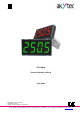
User manual

akYtec GmbH · Vahrenwalder Str. 269 A · 30179 Hannover · Germany Tel.: +49 (0) 511 16 59 672-0 · www.akytec.de
3
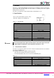
3 Intended use
The device may only be used in the manner described in this user guide, properly installed
and in accordance with the specification. Damages caused by disregarding the instructions
of this manual are without liability.
Non-observance of the safety guidelines may result in damage to the device and injury to
personal.
Improper use
Any other use is considered improper. Especially to note:
– The ITP11 may not be used for medical devices that sustain, monitor or otherwise affect
human life or health.
– The device may not be used if the environmental conditions (temperature, humidity etc.)
are not within the limits indicated in the specification.
– The device may not be used in potentially explosive environment or in an atmosphere
with chemically active substances.
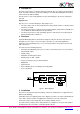
4 Functions
A 4-digit LED display with 14 mm character height is located on the front of the device to
display the process value or error messages in operation (see 6) and programming
parameters in programming mode (see 7). The function buttons are positioned on the rear
part of the device.
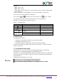
The device has the following functions:
− Measuring and displaying of the process value, received from a process control device
with 4-20 mA output
− Signal scaling
− Adjustable decimal point position
− Display range of -999…+9999
− Square root function (for special transmitters)
− Digital filter
− Alarm function
− Error indication when exceeding the measuring limits
− Access protection
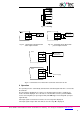
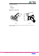
Fig. 4.1 Block diagram
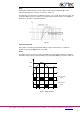
5 Installation
The device is designed for panel mounting in a borehole of Ø22.5 mm (see Appendix A for
dimensional drawings).
Carefully position the supplied gasket on the display rear surface. Insert the cylindrical body
of the device into the borehole and tighten the nut from the rear side of the panel.
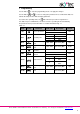
Connect the device to the signal cable in accordance with Fig. 5.2-5.4.
The device factory settings can be changed before assembly if necessary. For this purpose
the display must be connected to a standard signal 4-20 mA.