
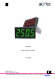
User manual

akYtec GmbH · Vahrenwalder Str. 269 A · 30179 Hannover · Germany Tel.: +49 (0) 511 16 59 672-0 · www.akytec.de
4
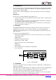
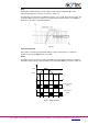
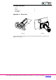
Fig. 5.1 Mounting
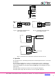
Fig. 5.2 Connection to the device with
active output 4-20mA
Fig. 5.3 Connection to the device with
passive output 4-20mA
Fig. 5.4 Connection of 2 or more ITP11 to the one source of 4-20 mA
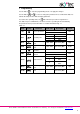
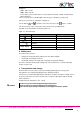
6 Operation
The operating mode is automatically activated if the standard signal 4-20 mA is connected to
the terminals.
The input signal is digitalised, the square root calculated (if the function is enabled), the
result scaled and displayed. The scale factor is calculated based on the parameter di.Lo
“Lower measuring limit” (for input signal 4 mA) and di.Hi “Upper measuring limit” (for input
signal 20 mA).
If the input signal is lower than 3.8 mA, the error message Lo is displayed.
If the input signal is higher than 22.5 mA, the error message Hi is displayed.
+
+
+
1
2
Device with
AO 4-20 mA
Power supply
ITP11
+
1
2
Device with
AO 4-20 mA
+
Power supply
ITP11
+
1
2
ITP11
...
...
+