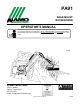
PA91 REAR-MOUNT BOOM MOWER Part No. 7191852C Published 03/09 OPERATOR’S MANUAL This Operator's Manual is an integral part of the safe operation of this machine and must be maintained with the unit at all times. READ, UNDERSTAND, and FOLLOW the Safety and Operation Instructions contained in this manual before operating the equipment. C01Cover ALAMO INDUSTRIAL ® 1502 E. Walnut Seguin, Texas 78155 830-372-3551 Email: parts@alamo-industrial.com ©2009 Alamo Group Inc. $0.
To the Owner/Operator/Dealer All implements with moving parts are potentially hazardous. There is no substitute for a cautious, safe-minded operator who recognizes the potential hazards and follows reasonable safety practices. The manufacturer has designed this implement to be used with all its safety equipment properly attached to minimize the chance of accidents. BEFORE YOU START!!Read the safety messages on the implement and shown in your manual.
In order to reduce accidents and enhance the safe operation of mowers, Alamo Industrial, in cooperation with other industry manufacturers has developed the AEM/FEMA Industrial and Agricultural Mower Safety Practices video and guide book. The video will familiarize and instruct mower-tractor operators in safe practices when using industrial and agricultural mowing equipment.
Alamo Industrial Division is willing to provide one (1) AEM Mower Safety Practices Video Please Send Me: VHS Format – AEM/FEMA Mower Operator Safety Video DVD Format – AEM/FEMA Mower Operator Safety Video Mower Operator’s Manual AEM Mower Operator’s Safety Manual Requester Name Phone: Requester Address: City State Zip Code Mower Model: Serial Number: Date Purchased: Dealer Salesperson: Dealership Name: Dealership Location: Mail to: AEM Video Services 1502 E Walnut street Seguin, TX 78155 Or Fax t
TABLE OF CONTENTS SAFETY SECTION .............................................................................................................. 1-1 General Safety Instructions and Practices ......................................................................................................... 1-2 Operator Safety Instructions and Practices ....................................................................................................... 1-3 Equipment Operation Safety Instructions and Practices .......
Operator Thrown Object Protection ................................................................................................................... 4-5 Tractor Lighting and SMV Emblem .................................................................................................................... 4-6 Tractor Ballast .................................................................................................................................................... 4-7 Tractor Safety Devices .............
HYDRAULIC PUMPS ........................................................................................................................................ 5-4 FLAILHEAD ....................................................................................................................................................... 5-4 CABLE OPERATED ARMHEAD CONTROL VALVE ........................................................................................ 5-5 Replacing Damaged or Worn Spool “O” Rings .................
SAFETY SECTION Safety Section 1-1 © 2009 Alamo Group Inc.
SAFETY General Safety Instructions and Practices SAFETY A careful operator is the best operator. Safety is of primary importance to the manufacturer and should be to the owner/operator. Most accidents can be avoided by being aware of your equipment, your surroundings, and observing certain precautions. The first section of this manual includes a list of Safety Messages that, if followed, will help protect the operator and bystanders from injury or death.
SAFETY Engine Exhaust, some of its constituents, and certain vehicle components contain or emit chemicals known to the state of California to cause cancer and birth defects or other reproductive harm. (SG-30) Battery posts, terminals and related accessories contain lead and lead compounds, chemicals known to the state of California to cause cancer, birth defects or other reproductive harm. (SG-31) The rotating parts of this machine continue to rotate even after the PTO has been turned off.
SAFETY SAFETY PROLONGED EXPOSURE TO LOUD NOISE MAY CAUSE PERMANENT HEARING LOSS! Tractors with or without an Implement attached can often be noisy enough to cause permanent hearing loss. We recommend that you always wear hearing protection if the noise in the Operator’s position exceeds 80db. Noise over 85db over an extended period of time will cause severe hearing loss. Noise over 90db adjacent to the Operator over an extended period of time will cause permanent or total hearing loss.
SAFETY Use extreme caution when getting onto the Implement to perform repairs, maintenance and when removing accumulated material. Only stand on solid flat surfaces to ensure good footing. Use a ladder or raised stand to access high spots which cannot be reached from ground level. Slipping and falling can cause serious injury or death. (SG-33) DO NOT operate this Implement on a Tractor that is not properly maintained.
SAFETY Use extreme care when lowering or unfolding the implement’s wings. Make sure no bystanders are close by or underneath the wings. Allow ample clearance around the implement when folding or unfolding the wings. Use extreme caution around buildings or overhead power lines. (S3PT-05) SAFETY This Implement is wider than the Tractor.
SAFETY Never allow children to operate, ride on, or come close to the Tractor or Implement. Usually, 16-17 year-old children who are mature and responsible can operate the implement with adult supervision, if they have read and understand the Operator’s Manuals, been trained in proper operation of the tractor and Implement, and are physically large enough to reach and operate the controls easily. (SG-11) Start tractor only when properly seated in the Tractor seat.
SAFETY Operate the Tractor and/or Implement controls only while properly seated in the Tractor seat with the seat belt securely fastened around you. Inadvertent movement of the Tractor or Implement may cause serious injury or death. (SG-29) In case of mechanical difficulty during operation, place the transmission in the park position, set the parking brake, shut down all power, including the PTO and the engine and remove the key. Wait until all rotating motion has stopped before dismounting.
SAFETY Extreme care should be taken when operating near loose objects such as gravel, rocks, wire, and other debris. Inspect the area before mowing. Foreign objects should be removed from the site to prevent machine damage and/or bodily injury or even death. Any objects that cannot be removed must be clearly marked and carefully avoided by the operator. Stop mowing immediately if blades strike a foreign object. Repair all damage and make certain rotor or blade carrier is balanced before resuming mowing.
SAFETY Follow these guidelines to reduce the risk of equipment and grass fires while operating, servicing, and repairing the Mower and Tractor: -Equip the Tractor with a fire extinguisher in an accesible location. -Do Not operate the Mower on a Tractor with an underframe exhaust. -Do Not smoke or have an open flame near the Mower and Tractor. -Do Not drive into burning debris or freshly burnt areas. SAFETY -Ensure slip clutches are properly adjusted to prevent excessive slippage and plate heating.
SAFETY Rotary Mowers are capable under adverse conditions of throwing objects for great distances (300 feet or more) and causing serious injury or death. Follow safety messages carefully.
SAFETY Always shut the Tractor completely down, place the transmission in park, and set the parking brake before you or anyone else attempts to connect or disconnect the Implement and Tractor hitches. (S3PT-15) SAFETY Never operate the Tractor and Mower if the Implement input driveline is directly connected to the Tractor transmission.
SAFETY Make certain that the “Slow Moving Vehicle” (SMV) sign is installed in such a way as to be clearly visible and legible. When transporting the Equipment use the Tractor flashing warning lights and follow all local traffic regulations. (SG-6) Before transporting the Tractor and Implement, determine the proper transport speeds for you and the equipment. Make sure you abide by the following rules: Test the tractor at a slow speed and increase the speed slowly.
SAFETY Your driving vision may be reduced or impaired by the tractor, cab, or implement. Before driving on public roadways identify any limited vision areas, and make adjustments to your operating position, mirrors, and the implement transport position so that you can clearly see the area where you will be traveling, and any traffic that may approach you. Failure to maintain adequate vision of the public roadway and traffic can result in serious injury or even death.
SAFETY Periodically inspect all moving parts for wear and replace when necessary with authorized service parts. Look for loose fasteners, worn or broken parts, and leaky or loose fittings. Make sure all pins have cotter pins and washers. Serious injury may occur from not maintaining this machine in good working order. (SG-21) Perform service, repairs and lubrication according to the maintenance section.
SAFETY PARTS INFORMATION Alamo Industrial mowers use balanced and matched system components for blade carriers, blades, cuttershafts, knives, knife hangers, rollers, drivetrain components, and bearings. These parts are made and tested to Alamo Industrial specifications. Non-genuine "will fit" parts do not consistently meet these specifications. The use of “will fit” parts may reduce mower performance, void mower warranties, and present a safety hazard.
SAFETY Decal Location NOTE: Alamo Industrial supplies safety decals on this product to promote safe operation. Damage to the decals may occur while in shipping, use, or reconditioning. Alamo Industrial cares about the safety of its customers, operators, and bystanders, and will replace the safety decals on this product in the field, free of charge (Some shipping and handling charges may apply). Contact your Alamo Industrial dealer to order replacement decals. SAFETY PA91 03/09 © 2009 Alamo Group Inc.
SAFETY SAFETY ITEM PART NO. QTY LEVEL DESCRIPTION 1. 2. 3. 4. 5. 6. 7. 8. 9. 10. 11. 12. 13. 14. 15. 16. 17. 18. 19. 20. 21. 22. 23. 24. 25. 26. 27. 28. 29. 30. 31. 32. 33. 34. 35. 36. 37. 38.
SAFETY Decal Description Danger! Mult-Hazard Warning. Failing to follow these Safety Messages and Operating Instructions can cause serious bodily injury or even death to operator and others in the area. SAFETY P/N 002369 PA91 03/09 © 2009 Alamo Group Inc.
SAFETY DANGER! - Multi-Hazard Boom. Take precautions while transporting and operating Boom Unit. SAFETY P/N 02958241 WARNING! Failure to INSPECT and REPAIR or REPLACE Hoses may allow worn Hoses to rupture SUDDENLY and VIOLENTLY with resulting serious BODILY INJURY from SCALDING or FIRE with resulting BURN INJURY or DEATH. P/N 02965262 IMPORTANT - Use only Genuine Alamo Industrial replacement parts. P/N 02925100 WARNING! Pinch Points P/N 02962764 PA91 03/09 © 2009 Alamo Group Inc.
SAFETY DANGER! Crushing and Pinch Points. Moving machiney parts can pinch or crush or fallwhich may cause injury or death. INFORMATION - To prevent premature hydraulic component failure, do not over speed the engine. When using the mower attachment, operate tractor at the engine speed which will deliver 540 PTO RPM on Tachometer. Over speeding the engine and pump when operating the mower will overheat and rapidly ruin the oil which will decrease the life of the hydraulic components.
SAFETY WARNING: Pressurized Tank SAFETY 03200437 DANGER! Keep Away Thrown Objects. Inspect the area before mowing for potential mower hazards. Remove or avoid all foreign objects such as wire, cable, metal objects, and all other foreign material. Foreign material can be thrown from the mower and cause serious bodily injury to the operator and passerby. Do Not let rotating blades contact solid objects like rocks, posts, curbs or guard rails.
SAFETY WARNING! Keep all safety shielding installed, repaired and replaced when damaged so that machine stays in safe condition. P/N 00756007 SAFETY DANGER! Keep Away - Rotating Blades P/N 00756485 DANGER! Make certain that drivelines are correct length and are securely attached. P/N 00756494 DANGER! - Multi-Hazard Boom. Take precautions while transporting and operating Boom Unit. P/N 02958241 PA91 03/09 © 2009 Alamo Group Inc.
SAFETY Information that Grease Fitting is present and must apply grease. SAFETY P/N 000678 Instructions to properly lubricate and check mower for potential problems prior to operation. P/N 000108 INFORMATION - Attention - Service Hydraulic System with Universal Tractor Hydraulic Oil. Alamo Group part Number 02966307. 02966305 Peligro Translation, If you do not know how to read English, please find someone who knows how to read English. P/N 00725746 PA91 03/09 © 2009 Alamo Group Inc.
SAFETY WARNING! Avoid Bodily Injury, Use 540RPM PTO Speed Only. Slow Moving Vehicle Decal. Keep SMV reflector clean and visible. DO NOT transport or operate without the SMV. P/N 03200347 Red Reflector. Keep reflectors clean and visible. P/N 1458392 Amber Reflector. Keep reflectors clean and visible. P/N 1458393 PA91 03/09 © 2009 Alamo Group Inc.
SAFETY PELIGRO! Spanish Translation for Driveline Safety SAFETY P/N 00773723 ALAMO INDUSTRIAL LOGO P/N 001651 ALAMO NAME LOGO. P/N 001650 Read Operator’s Manual! The operator’s manual is located inside this canister. If the manual is missing order one from your dealer. P/N 00776031 PA91 03/09 © 2009 Alamo Group Inc.
SAFETY Federal Laws and Regulations This section is intended to explain in broad terms the concept and effect of federal laws and regulations concerning employer and employee equipment operators. This section is not intended as a legal interpretation of the law and should not be considered as such. Employer-Employee Operator Regulations U.S. Public Law 91-596 (The Williams-Steiger Occupational and Health Act of 1970) OSHA This Act Seeks: DUTIES Sec.
INTRODUCTION SECTION Introduction Section 2-1 © 2009 Alamo Group Inc.
INTRODUCTION This trimmer is designed with care and built with quality materials by skilled workers. Proper assembly, maintenance, and operating practices, as described in this manual, will help the owner/ operator get years of satisfactory service from the machine. The purpose of this manual is to familiarize, and instruct. The Assembly Section instructs the owner/operator in INTRODUCTION the correct assembly of the Mower using standard and optional equipment.
INTRODUCTION INTRODUCTION These hydraulically driven flail trimmers are designed for medium-duty work. They can mow pastures and control grass and weeds on highways or industrial sites. For Non-Agricultural use, OSHA, ASAE, SAE and ANSI standards require the use of Chain Guards, Deflectors, or Solid Skirts at all times.
INTRODUCTION ATTENTION OWNER/ OPERATOR BEFORE OPERATING THIS MACHINE: 1. Carefully read the Operator’s Manual, completely understand the Safety Messages and instructions, and know how to operate correctly both the Mower and Power Unit. INTRODUCTION 2. Fill out the Warranty Card in full. Be sure to answer all questions, including the Serial Number of the Mower. Mail promptly using the return envelope included with the Operator’s Manual.
ASSEMBLY SECTION Assembly Section 3-1 © 2009 Alamo Group Inc.
ASSEMBLY TRACTOR SELECTION ASSEMBLY Horsepower and Weight Requirements The Power Arm 91 requires a tractor with a minimum of 30 HP in conjunction with a minimum weight of 1500Kg (1.5 tons imp. 1.6 tons U.S.). If necessary, add ballast to achieve this weight. Check in the tractor’s handbook that it does not exceed the maximum allowed. Bear in mind that these are minimum requirements for optimum working conditions.
ASSEMBLY TRACTOR PREPARATION Fitting Operator Guard A tractor fitted with a cab that has a safety glass windows should be used whenever possible. This is a basic safety precaution applicable to the use of all flail-type hedge trimmers. Power arms are supplied with an operator guard kit (Part No. 73 13 324) which must be fitted to the tractor before commencing work.
ASSEMBLY ASSEMBLY Ballast Weight Tractor must be stable while operating the hedge cutters under all conditions. Pay attention when operating on slopes. Front end ballast as well as rear wheel weights to counterbalance the overhang of the flail head should be added as appropriate. On steeply banked ground, it may not be sufficient to depend alone on the counterweight provided by the oil reservoir. In addition, rear wheel track should be set as wide as possible to increase stability.
ASSEMBLY DELIVERY 1. The machine is delivered in a partially dismantled condition. To make ready for attachment to the tractor it will be necessary to select a hard level surface 2. Cut the banding straps and remove the attached articles. 3. Fill the reservoir to capacity with oil selected from the chart on Section 3-9 to increase the stability of the machine. 4. Remove and discard the transport strap connecting the flail head to the frame and also the lift ram stop strapped to the rod. Si Model 1.
ASSEMBLY ASSEMBLY *This measurement which is the fully closed final length of the PTO drive shaft measured button to button should be taken carefully before the PTO drive shaft is shortened to suit by cutting off both the driving and driven members of the tube by an equal amount. Likewise, the plastic shield will similarly have to be cut. Take heed if too much is cut, it cannot be stuck back on. Measure twice and cut once.
ASSEMBLY ASSEMBLY This procedure is for initial attachment only, for subsequent attachment paras marked * do not apply. If it is required to mount the machine on a different tractor, bear in mind that the engagement of the PTO shaft will alter. A safe minimum engagement between the two halves of the shaft is 6”. This dimension must be checked before work is commenced. PA91 03/09 © 2009 Alamo Group Inc.
ASSEMBLY FITTING CONTROL UNIT IN CAB ASSEMBLY The 3 lever control unit which is cable operated is mounted on an adjustable stalk that is attached to a seat bracket which is of universal design for mounting in many models of tractor. The bracket is normally trapped between the seat runners and their mounting base. It may sometimes be necessary to drill extra holes in the seat bracket to find the ideal operator position.
ASSEMBLY OIL REQUIREMENTS Tank The machine is delivered from the factory without oil. Fill the reservoir with a light hydraulic oil as recommended in the chart until the oil level is approximately 2” below the top of the tank. The total capacity is approximately 117 tires (25 gallons). Do not overfill. The oil must have anti-frothing characteristics suitable for use in hydraulic systems.
ASSEMBLY ASSEMBLY RUNNING UP PROCEDURE PA91 Ti 1. Ensure that the rotor control is in “STOP” position, start the tractor, engage PTO and allow the oil to circulate for about 5 minutes without operation of the armhead control lever. This will allow all the oil to circulate thoroughly through the return line filter. 2. Operate the armhead levers through their complete range ensuring that all movements are functioning correctly. 3.
ASSEMBLY REMOVAL FROM TRACTOR STORAGE If machine is to be left standing for an extended period of time, lightly coat the exposed portions of the ram rods with grease. Subsequently, this grease which becomes contaminated with dust and grit should be wiped off before the rams are next moved. If the machine has to be stored outside, tie a piece of tarpaulin or canvas over the control assembly. Do not use a plastic fertilizer bag which could lead to rapid corrosion. PA91 03/09 © 2009 Alamo Group Inc.
ASSEMBLY PROPER TORQUE VALUES FOR FASTENERS The chart lists the correct tightening torque for fasteners. When bolts are to be tightened or replaced, refer to this chart to determine the grade of bolts and the proper torque except when specific torque values are assigned in manual text. ASSEMBLY RECOMMENDED TORQUE IN FOOT POUNDS UNLESS OTHERWISE STATED IN THE MANUAL* NOTE: These values apply to fasteners as received from supplier, dry or when lubricated with normal engine oil.
OPERATION SECTION Operation Section 4-1 © 2009 Alamo Group Inc.
OPERATION ALAMO INDUSTRIAL POWER ARM 91 OPERATING INSTRUCTIONS OPERATION Alamo Industrial Interstater flail mowers are manufactured with quality material by skilled workers. These mowers are designed for cutting grass and small weeds. The mower is equipped with protective deflectors to prevent objects being thrown from the mower by the blades, however, no shielding is 100% effective. All shields, guards, and deflectors equipped on the mower must be maintained in good operational condition.
OPERATION 1. Standard Equipment and Specifications Standard Specifications Welded Tubular Frame CAT I or CAT II Three Point Hitch 24-Gallon Reservoir with 12 Micron Filtration OPERATION Self-Contained Hydraulics Hydraulic Breakaway 3-Spool Valve with Work Port Reliefs 1-1/2” King Post Inner Boom Arm Tubing: 4” x 4” x 3/16” Outer Boom Arm Tubing: 4” x 4” x 1/4” Boom Reach: Up - 12’10”, Out - 12’8”, Do n- 7’10” Safety Cage (ROPS Units Only) Weight Approx.
OPERATION 2. OPERATOR REQUIREMENTS OPERATION Safe operation of the unit is the responsibility of a qualified operator. A qualified operator has read and understands the implement and tractor Operator’s Manuals and is experienced in implement and tractor operation and all associated safety practices. In addition to the safety messages contained in this manual, safety signs are affixed to the implement and tractor.
OPERATION 3. TRACTOR REQUIREMENTS In addition to tractor horsepower and size required to operate the mower unit, the tractor must also be properly equipped to provide operator protection, to alert approaching vehicle drivers of the tractor’s presence, and to ensure tractor stability when mowing with the boom fully extended. Tractor Requirements and Capabilities ASAE approved Roll-Over Protective Structure (ROPS) or ROPS cab and seat belt. Tractor Safety Devices .....................
OPERATION Never operate the Tractor and Mower Unit without an OPS (Operators Protective Structure) or Cab to prevent injury from objects thrown from ground or from overhead trimming. Stop mowing if workers or passersby are with in 100 yards. (SBM-9) OPERATION 3.3 Tractor Lighting and SMV Emblem If the tractor will be operated near or traveled on a public roadway it must be equipped with proper warning lighting and a Slow Moving Vehicle (SMV) emblem which are clearly visible from the rear of the unit.
OPERATION 3.4 Tractor Ballast For additional information on properly ballasting the tractor, refer to Alamo Industrial Tractor and Mower Stability Pamphlet P/N #02959010 If the unit is operated on slopes greater than 5°, additional counterweight will be required. Operation of the unit on slopes greater than 11 percent (6.4 degrees) is not recommended under any circumstances. On a tractor with a 96” outside to outside tire spread, an 11 percent (6.
OPERATION 3.7 3-Point Hitch OPERATION PA91 boom mowers can attach to tractors with either a CAT I or II hitch. Refer to the tractor operator’s manual for the category of the tractor used. If the hitch does not conform to ASAE Cat I or II dimensions, the mower may not fit or raise properly. Consult an authorized dealer for possible modification procedures to mount nonconforming hitches. Use the correct hitch pins for the hitch category being used.
OPERATION 3.10 Power Take Off (PTO) Depending on the unit, the mower is designed to operate at a PTO speed of 540 or 1000 RPM. Most tractors operate at either 540, or a combination of 540 and 1000 RPM PTO speeds. The operating speed of the mower and tractor can be determined by the number of splines on the driveline yoke and PTO output shaft. Those operating at 540 RPM will have a 6-spline shaft and those operating at 1000 RPM will have a 21-spline shaft or a 1-3/4” 20 spline shaft.
OPERATION 4.1 Boarding the Tractor Use both hands and equipped handrails and steps for support when boarding the tractor. Never use control levers for support when mounting the tractor. Seat yourself in the operator’s seat and secure the seat belt around you. OPERATION Never allow passengers to ride on the tractor or attached equipment. Riders can easily fall off and be seriously injured or killed from falling off and being ran over.
OPERATION 5. STARTING THE TRACTOR The operator must have a complete understanding of the placement, function, and operational use of all tractor controls before starting the tractor. Review the tractor operator’s manual and consult an authorized dealer for tractor operation instructions if needed.
OPERATION 5.1 Connecting Attaching Head to the Boom OPERATION 1. Start by using a hoist to lower the boom(1) down to the mower head (6). Align the Boom with the Head Hitch Post(7), insert the upper hitch pin(2) through the top hole of the Head Hitch Post (7) and upper linkage (11). Attach with bolt (8), washer(9) , and nut (10). 2. Then align the lower linkage (12) of the Boom and insert the lower hitch pin(3) through lower hole of hitch post(7).Attach with bolt (8),washer (9) and nut(10). 3.
OPERATION Always shut the Tractor completely down, place the transmission in park, and set the parking brake before you or anyone else attempts to connect or disconnect the Implement and Tractor hitches. (S3PT-15) All Safety Shields, Guards and Safety devices including (but not limited to) - the Deflectors, Chain Guards, Steel Guards, Gearbox Shields, PTO integral shields , and Retractable Door Shields should be used and maintained in good working condition.
OPERATION 6. PRE-OPERATION INSPECTION AND SERVICE OPERATION Before each use, a pre-operation inspection and service of the implement and tractor must be performed. This includes routine maintenance and scheduled lubrication, inspecting that all safety devices are equipped and functional, and performing needed repairs. DO NOT operate the unit if the pre-operation inspection reveals any condition affecting safe operation. Perform repairs and replacement of damaged and missing parts as soon as noticed.
OPERATION 6.2 Boom Unit Pre-Operation Inspection and Service Inspect and service the boom arm and head prior to operation. Damaged and/or broken parts should be repaired and/or replaced immediately. To ensure the unit is ready for operation, conduct the following: OPS-B- 0020 Replace bent or broken blades with new blades.
OPERATION FRAME ASSEMBLY • • • • OPERATION • Inspect condition of mounting frame weldment. Inspect condition of King Post frame. Ensure all bolts and screws are in position and are properly torqued. Ensure all pins are in place and fastened with screws. Ensure frame is properly mounted to tractor and hardware is propely installed and tightened. OPS-B- 0021_D BOOM ARM ASSEMBLY • • • • • • Inspect condition of each arm section weldment Ensure all pins are in place.
OPERATION Relieve hydraulic pressure prior to doing any maintenance or repair work on the Implement. Place the Mower Head on the ground or securely supported on blocks or stands, disengage the PTO, and turn off the engine. Push and pull the control Levers or Joystick several times to relieve pressure prior to starting any maintenance or repair work. (SBM-6) Never Leave the mower unattended while the head is in the raised position.
OPERATION OPERATION Do not operate this Equipment with hydraulic oil or fuel leaking. Oil and fuel are explosive and their presence could present a hazard. Do not check for leaks with your hand! High-pressure oil streams from breaks in the line could penetrate the skin and cause tissue damage including gangrene. To check for a hose leak, SHUT the unit ENGINE OFF and remove all hydraulic pressure. Wear oil impenetrable gloves, safety glasses and use Cardboard to check for evidence of oil leaks.
OPERATION Boom Mower PRE-OPERATION Inspection Mower ID#________________ Make ____________________ Date: Shift ________________ ____________________ Condition at Start of Shift Item Specific Comments if not O.K.
OPERATION OPERATION Tractor PRE-OPERATION Inspection Mower ID#________________ Make ____________________ Date: Shift ________________ ____________________ Before conducting the inspection, make sure the tractor engine is off, all rotation has stopped and the tractor is in park with the parking brake engaged. Make sure the mower is resting on the ground or securely blocked up and all hydraulic pressure has been relieved. Condition at Start of Shift Item Specific Comments if not O.K.
OPERATION 7. OPERATING THE BOOM MOWER 7.1 Machine Controls OPERATION Moving the Arm control levers away from the cables will result in “LIft Down”, “Angle Down” and “Reach Out”. For Ti Models only, the Flail On/Off valve can be mounted on either end of the main control block. It is delivered with the lever control gate set in the position limiting the lever selection to “Flail Off” and “Flail On - Upwards Cut”.
OPERATION 7.3 Forward Speed Tractor ground speed is determined by common sense and experience. It should be slow enough to allow sufficient time for the flails to cut the work without overloading. It is obviously better to make a second pass or more in heavier growth to avoid undue strain. 7.4 Tractor Position OPERATION The position of the tractor in relation to the hedgerow will again be determined by experience.
OPERATION 7.9 Hedge Cutting Procedure Upward Cutting Front Flap Kit (Optional Extra) To further reduce the possibility of debris being thrown out of the front of the hood a flap kit consisting of seven rubber flaps which are attached to the leading edge of front hood is available. Optional Downward Cutting It is possible to reverse the rotation of the flail for downward cutting. This chopping action subjects the rotor to a more violent usage and should therefore be avoided whenever possible.
OPERATION Reversing Rotation (Si Only) Fully extend the armhead and lower flail to the ground to minimize oil loss. Release the rotor hoses from either the flail motor or the rotor control valve and interchange the connections. Do not cross over the flail supply and return hoses at any other point as the hose routing and cross overs in the installation are necessary to allow the hoses to flex correctly during arm movements. To ascertain the direction of cut without running the machine the following applies.
OPERATION 7.10 Lift Float Kit (Optional) OPERATION Ground scrub flailing can be a slow tedious task requiring a high degree of operator concentration especially when working on a rough or rising ground. A hydraulic float kit is available which is mounted tap upwards through the inboard mounting hole of a bracket which is located and bolted vertically to the face of the lift ram base lug nearest the tractor. See Illustration.
OPERATION OPERATION 7.11 Flail Types Two types of flail are available: The F91 H is a cast flail suitable for continuous hedge and scrub cutting. It will also cut grass, but the finish will be inferior to that produced by the F91 G and the power requirements greater. The F91 G is a pressed flail suitable for grass and scrub cutting. It can also be used to cut hedges, but continuous use in this material will noticeably shorten its working life. 7.
OPERATION 8. DRIVING THE TRACTOR AND IMPLEMENT Safe tractor transport requires the operator to possess a thorough knowledge of the model being operated and precautions to take while driving with an attached implement. Ensure the tractor has the capacity to handle the weight of the boom and the tractor operating controls are set for safe transport. To ensure safety while driving the tractor with a boom, review the following. Power for operating the mower is supplied from the tractor PTO.
OPERATION Transport only at speeds where you can maintain control of the equipment. Serious accidents and injuries can result from operating this equipment at high speeds. Understand the Tractor and Implement and how it handles before transporting on streets and highways. Make sure the Tractor steering and brakes are in good condition and operate properly. OPERATION Before transporting the Tractor and Implement, determine the proper transport speeds for you and the equipment.
OPERATION 8.2 Brake and Differential Lock Setting Always disengage the tractor differential lock when turning. When engaged the differential lock will prevent or limit the tractor from turning. During normal cutting conditions, locking the differential provides no benefit and should not be used. OPS-U- 0013 Be aware of the operating conditions. Do not operate the Tractor with weak or faulty brakes.
OPERATION 8.3 Transport Position • OPERATION • • • • • • For transport on public highway, the boom must be folded within the overall width of the tractor.Position the arm until the boom head is approximately 4 ft. (1.5 M) clear of the ground and the dipper is horizontal. Pull the dipper arm to the rear to remove tension on the breakaway ram base pin and remove it. Manually break back the dipper until the base of the ram is relocated between the inboard holes in the ram lugs. Replace the ram base pin.
OPERATION 8.4 Driving the Tractor and Boom Start off driving at a slow speed and gradually increase your speed while maintaining complete control of the tractor. Never operate the tractor at speeds that cannot be safely handled or which will prevent the operator from stopping quickly during an emergency. If the power steering or engine ceases operating, stop the tractor immediately as the tractor will be difficult to control.
OPERATION 9. OPERATING THE TRACTOR AND IMPLEMENT OPERATION THE OPERATOR MUST COMPLETELY UNDERSTAND HOW TO OPERATE THE TRACTOR AND IMPLEMENT AND ALL CONTROLS BEFORE ATTEMPTING TO OPERATE. The operator must read and understand the Safety and Operation Sections of the implement and tractor operator’s manuals. These manuals must be read and explained to any operator who cannot read. Never allow someone to operate the implement and tractor without complete operating instructions.
OPERATION When cutting foliage and fine shredding is desired, run the mower level or slightly lower in the rear so as to keep the material in the mower until it is shredded. This will require more power but will shred better. When cutting heavy foliage and fine shredding is not desired, raise the rear of the mower. This will allow the high volume of material to be discharged and requires much less power. Do not ride the clutch on the tractor. Mow in the appropriate gears to give the correct ground speed.
OPERATION 9.2 Foreign Debris Hazards OPERATION Before mowing, inspect the area to make sure there are no foreign objects that the mower blades could hit or become entangled with. Remove all foreign objects and debris. If objects are too big to remove, mark them clearly and be sure to prevent the mower blades from contacting them. If you hit a solid object or foreign debris, stop the mower and tractor at once. Immediately idle the engine speed and disengage the PTO.
OPERATION Rotary Mowers are capable under adverse conditions of throwing objects for great distances (300 feet or more) and causing serious injury or death. Follow safety messages carefully.
OPERATION 9.5 Operating Speed and Ground Speed OPERATION Ground speed for mowing will depend upon the height, type, and density of vegetation to be cut. Do Not exceed 2 MPH while operating. Operate the mower at its full rated PTO speed to maintain blade speed for a clean cut. Refer to the tractor operator’s manual or the tractor instrument panel for the engine speed and gear to provide the required operating and desired ground speed.
OPERATION There are obvious and hidden potential hazards in the operation of this Mower. REMEMBER! This machine is often operated in heavy brush and in heavy weeds. The Blades of this Mower can throw objects if shields are not properly installed and maintained. Serious injury or even death may occur unless care is taken to insure the safety of the operator, bystanders, or passersby in the area. Do not operate this machine with anyone in the immediate area. Stop mowing if anyone is within 100 yards of mower.
OPERATION 9.7 Shutting Down the Attached Head OPERATION To shut down attached mower head, first bring the tractor to a complete stop. Decrease engine RPM to idle then disengage cutterhead. The mower head will come to a complete stop within a suitable amount of time. Do not engage or disengage the cutterheads at a high RPM unless there is an emergency situation.
OPERATION 9.8 TRACTOR, BOOM, AND ATTACHED HEAD STORAGE Properly preparing and storing the unit at the end of the season is critical to maintaining its appearance and to help ensure years of dependable service. The following are suggested storage procedures: • • • • • Never allow children to play on or around Tractor or Implement. Children can slip or fall off the Equipment and be injured or killed. Children can cause the Implement to shift or fall crushing themselves or others.
OPERATION 10. TRANSPORTING THE TRACTOR AND IMPLEMENT OPERATION Inherent hazards of operating the tractor and implement and the possibility of accidents are not left behind when you finish working in an area. Therefore, the operator must employ good judgement and safe operation practices when transporting the tractor and implement between locations. By using good judgement and following safe transport procedures, the possibility of accidents while moving between locations can be substantially minimized.
OPERATION Only tow the Implement behind a properly sized and equipped Tractor which exceeds the weight of the Implement by at least 20%. DO NOT tow the Implement behind a truck or other type of vehicle. Never tow the Implement and another Implement connected in tandem. Never tow the Implement at speeds over 20 MPH. (STI-06) Never allow children or other persons to ride on the Tractor or Implement. Falling off can result in serious injury or death.
OPERATION OPERATION When operating on public roads, have consideration for other road users. Pull to the side of the road occasionally to allow all following traffic to pass. Do not exceed the legal speed limit set in your country for agricultural tractors. Always stay alert when transporting the tractor and implement on public roads. Use caution and reduce speed if other vehicles or pedestrians are in the area. OPSU- 0022 Reduce speed before turning or applying the brakes.
OPERATION 10.2 Hauling the Tractor and Implement Before transporting a loaded tractor and implement, measure the height and width dimensions and gross weight of the complete loaded unit. Ensure that the load will be in compliance with the legal limits set for the areas that will be traveled through. OPS-U- 0024 Arrange the chains so that when tightened, the chains are pulling downward and against themselves.
OPERATION OPERATION 11. TROUBLESHOOTING GUIDE TROUBLE POSSIBLE CAUSE POSSIBLE REMEDY Hydraulic Cylinder Not Working Hydraulic level low. Check hydraulic fluid level. (See sight gauge on tank) Attempt to use another cylinder or pressure gauge. Check line for stoppage. Pump not functioning properly. Cylinder not functioning properly. Cylinder has a scored wall, allow oil to flow around piston. Replace the cylinder. Hydraulic Motor Not Working Kinks or pinched points on the line.
OPERATION POSSIBLE CAUSE POSSIBLE REMEDY Structural Members Failure Rough treatment. Use only on elements it is designed to cut such as grass, weeds, brush, trees. Excessive Vibrations Check Gear box bolts. Check For loose nuts on bladeholder and blades Check for bent output shaft. If shaft is bent oil will normally leak from the bottom seal. Check to see if blades are free swinging. Check for even wear on each blade tip. Were both blades changed at the same time? Tighten if loose.
OPERATION OPERATION TROUBLE POSSIBLE CAUSE POSSIBLE REMEDY Gearbox Leaking Damaged oil seal Bent shaft. Shaft rough in oil seal area. Oil seal installed wrong. Oil seal not sealing in the housing. Oil level too high. Sand hole is casting. Gasket damaged. Bolts loose. Replace seal. Replace oil seal and shaft. Replace or repair shaft. Replace seal. Replace seal or use a sealant on OD of Seal. Drain oil to proper level. Replace castings or gearbox. Replace gasket. Tighten bolts.
MAINTENANCE SECTION Maintenance Section 5-1 © 2009 Alamo Group Inc.
MAINTENANCE LUBRICATION MAINTENANCE General Refer to the lubrication diagram and grease daily all the points shown. 1. Power take-off shaft - The PTO shaft should be regularly examined to ensure that it is in good condition together with the guards. The universal joints should be greased very sparingly, i.e., one shot a week. NOTE: Overgreasing a universal joint will blow out the cork or neoprene sealing rings that exclude the dirt from the needle bearing inside. 2.
MAINTENANCE HYDRAULIC SYSTEM Filtration Maintenance The machine is protected by a 125 micron suction strainer and a low pressure 10 micron full flow return line filter. 1. Suction Strainer The strainer is fixed in position within the reservoir. Should indications of pump cavitation or spongy intermittent operation occur the tank must be drained and flushed out with a suitable cleaning agent, e.g. clean diesel oil. 2.
MAINTENANCE MAINTENANCE HYDRAULIC PUMPS 1. All pumps are rotate clockwise. No routine maintenance is necessary other than a periodical check for tightness of the mounting bolts and a visual check for oil leakage especially around the pump supply and pressure unions. Where two hose clips are used on the pump supply hose, their worm drive barrels should be placed opposite each other at 180 degrees.
MAINTENANCE CABLE OPERATED ARMHEAD CONTROL VALVE Replacing Damaged or Worn Spool “O” Rings NOTE: Owing to the sharp edges in the design of the spool, failure to follow the above procedure could result in damage to the new “O” rings resulting in external leakage. 10. The spools are selectively assembled, matched with their mating bores in the block and should not be interchanged. PA91 03/09 © 2009 Alamo Group Inc. Maintenance Section 5-5 MAINTENANCE 1.
MAINTENANCE MAINTENANCE Main Relief Valve The main relief valve is pressure set at the factory to 1800 PSI (125 Bar) and is non-adjustable. A sticking relief valve will probably cause overheating and/or loss of power. If this is suspected, it should be dismantled and examined for dirt and damage. Undo the large hexagon housing, the relief valve spring, needle and seat can now be withdrawn.
MAINTENANCE HYDRAULIC RAMS Ram Seal Replacement - General Information Angling Arm Replacing Seals 1. Unscrew the gland and withdraw the complete rod assembly. Remove piston locking nut, slide the piston and gland housing of the rod. 2. Lubricate all new seals prior to assembly. 3. Replace the gland seals ensuring they are positioned in the same location from which they were removed. Carefully place the gland housing complete with seals back on the rod. 4. Separate the piston halves and discard rod seals.
MAINTENANCE ROTOR CONTROL VALVE/RELIEF VALVE Relief Valve MAINTENANCE The relief valve within the block is pre-calibrated to give setting of 3000 PSI (210 Bar). No servicing should be required other than cleaning and examining for damage should a malfunction occur. Evidence or damage will require a new component. Replacing Worn or Damaged “O” Rings 1. The cable and spring centering mechanism must be removed.
MAINTENANCE Replacing Shaft Seals HYDRAULIC HOSES The condition of all hoses should be carefully checked during routine service of the machine. Hoses that have been chafed or damaged on their outer casing should be securely wrapped with waterproof adhesive tape to stop the metal braid from rusting. Hoses that have suffered damage to the metal braid should be changed at the earliest opportunity. Hose Replacement 1. Replace one hose at a time to avoid the risk of wrong connections. 2.
ALAMO-INDUSTRIAL LIMITED WARRANTY 1. 2. LIMITED WARRANTIES 1.01. Alamo Industrial warrants for one year from the purchase date to the original non-commercial, governmental, or municipal purchaser (“Purchaser”) and warrants for six months to the original commercial or industrial purchaser 1.02. Manufacturer will replace for the Purchaser any part or parts found, upon examination at one of its factories, to be defective under normal use and service due to defects in material or workmanship. 1.03.
TO THE OWNER/OPERATOR/DEALER To keep your implement running efficiently and safely, read your manual thoroughly and follow these directions and the Safety Messages in this Manual. The Table of Contents clearly identifies each section where you can easily find the information you need. The OCCUPATIONAL SAFETY AND HEALTH ACT (1928.51 Subpart C) makes these minimum safety requirements of tractor operators: REQUIRED OF THE OWNER: 1.
PA91-SOM-02/08 Printed U.S.