BOOM ARM MOWER Published 07/06 (Rev 02-20-07) Part No. 02984405 ASSEMBLY MANUAL (STANDARD INSTRUCTIONS) Tractors equipped with additional options, special equipment, tractor manufacturer modifications, new tractor models, or Customer alterations may prevent this Mount Kit from being properly mounted to the tractor. Alamo Group is not responsible for modifications to the MountKit to accommodate these differences.
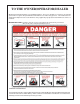
TO THE OWNER/OPERATOR/DEALER All implements with moving parts are potentially hazardous. There is no substitute for a cautious, safe-minded operator who recognizes the potential hazards and follows reasonable safety practices. The manufacturer has designed this implement to be used with all its safety equipment properly attached to minimize the chance of accidents. BEFORE YOU START!! Read the safety messages on the implement and shown in your manual.
NOTES Axtreme Boom General Assembly (02-06) (Rev 02-20-07) © 2006 Alamo Group Inc.
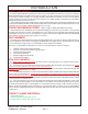
INTRODUCTION ABOUT THIS MANUAL: The intent of this publications to provide the competent technician with the information necessary to assemble the Alamo Industrial Product. This will, in turn provide for complete customer satisfaction. This manual is designed to be used as a basic component guide.
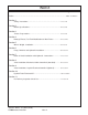
INDEX Section Page Index.......................................................................................................................... Index-1 to Index 2 Section 1 Safety Instructions.............................................................................. 1-1 to 1-6 Section 2 Model Specifications...........................................................................2-1 to 2-6 Section 3 Tractor Preperations.........................................................................
Section 1 Axtreme Boom SAFETY SECTION Axtreme Boom (Asy. Man.) 07/06 © 2006Alamo Group Inc.
Safety Section Read these assembly instructions through completely and understand them before proceeding with the assembly of the equipement. A safe and careful operator is the best operator. Safety is of primary importance to the manufacturer and should be to the owner/operator. Most accidents can be avoided by being aware of your equipment, your surroundings, and observing certain precautions.
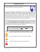
Safety Section PELIGRO! Si no lee Ingles, pida ayuda a alguien que si lo lea para que le traduzca las medidas de seguridad. (SG-3) !LEA EL INSTRUCTIVO! READ, UNDERSTAND, and FOLLOW the following Safety Messages. Serious injury or death may occur unless care is taken to follow the warnings and instructions stated in the Safety Messages. Always use good common sense to avoid hazards. (SG-2) ! PELIGRO!Si no lee Ingles, pida ayuda a alguien que si lo lea para que le traduzca las medidas de seguridad.
Safety Section WARNING! Many of the parts are heavy and require lifting assistance. Do not try to lift the heavy parts by yourself. Get help from another employee or from an overhead crane. WARNING! The operator and all support personnel should wear hard hats, safety shoes, safety glasses, and proper hearing protection at all times for protection from injury including injury from items thrown by the equipment. (SG-16) WARNING! Always wear safety shoes with steel toes when working on this equipment.
Safety Section DANGER! WARNING! Before starting the mower make sure the area is clear and the floor has been swept. The mower blade can throw objects several hundred feet. Thrown objects could damge property or cause severe bodily injuries even death. Make certain that the “Slow Moving Vehicle” (SMV) sign is installed in such a way as to be clearly visible and legible. When transporting the Equipment use the Tractor flashing warning lights and follow all local traffic regulations.
Safety Section DANGER! NEVER use drugs or alcohol immediately before or while operating the Tractor and Implement. Drugs and alcohol will affect an operator’s alertness and coordination and therefore affect the operator’s ability to operate the equipment safely. Before operating the Tractor or Implement, an operator on prescription or over-the-counter medication must consult a medical professional regarding any side effects of the medication that would hinder their ability to operate the Equipment safely.
Section 2 Axtreme Boom Model Specifications Axtreme Boom - Asy Man (07/06) © 2006 Alamo Industrial Section 2 - 1
SPECIFICATIONS - AXTREME BOOM READ THIS BEFORE BEGINNING ASSEMBLY: The Axtreme Boom has electronic components:. The electronic components can be damaged if care is not taken when performing repairs, testing and/or during assembly. DO NOT 1. 2. 3. 4. 5. 6. 7. 8. 9. 1. DO NOT short any wires across or allow them to be shorted out. DO NOT attempt to jump across any wires or supply them with alternate power source. DO NOT install higher rated fuses than are recommended by manufacturer.
SPECIFICATIONS - AXTREME BOOM 2. Fifty Inch (50") Cutting Head Specifications: Blade / Motor Rotation (Looking down from Top of Deck)...............Clockwise Blade Tip Speed........................................................................18,850 FPM / 210 MPH Blade carrier Type..................................................................... Pan or 3 Leaf bar Option Blade Pan Blade Qty................................................................. 2 Blade or 3 Blade Option Blade Bar Blade Qty..
SPECIFICATIONS - AXTREME BOOM 5. Control Valve: 5 Spool used with Rotary Heads w/ Door Valve Type................................................................................Open Center 5 Spool Valve Control (Manual Standard)................................................. Remote Cable Control Valve Control (Electonic Joystick Optional).................................. Joystick Electronic Control Pressure (Maximum).................................................................
Lift (Orange) Swing (Green) A "A" Port Side Dipper (Blue / White) Door (Yellow) Joystick Electronic Controled Valve (Optional) Tilt (Red / White) SPECIFICATIONS - AXTREME BOOM A A A A 1234567 1234567 1234567 1234567 1234567 12 12 12 12 12 12 12 1 1 2 2 2 12 12 12 123 123 123 Pressure Supply (Port P1) 3 12 12 12 4 7.
SPECIFICATIONS - AXTREME BOOM 8. Hose End Fitting Torque Specification: Hose End Type: 37 Degree Angle End Steel Hose End Fittings* Dash Nominal Cyl. Torque Torque Size Size (in.) in. lbs. ft .lbs. -4 1/4" 140 12 -6 3/8" 230 19 -8 1/2" 450 38 -10 5/8" 650 54 -12 3/4" 900 75 -16 1" 1200 100 -20 1-1/4" 1600 133 -24 1-1/2" 2000 167 -32 2" 2800 233 * Straight Threads do not always seal better when higher torgues are used. Too much torque causes distortion and may lead to leakage.
Section 3 Axtreme Boom Tractor Preperations NOTE: This shows a basic mount for the frame installation and may not be the same for your tractor model. The way the frame mounts to the tractor components can vary with tractor model. See the installation drawings shipped with the unit for the specific tractor type mount and hardware components.
General Information / Installation Requirements General Information: The tools you will need at the assembly site are as follows: 1. 2. 3. 4. 5. 6. 7. 8. 9. 10. 11. 12. 13. 14. Welding equipment (including correct head gear, eye shields, and protective clothing.) Impact wrench or socket and ratchet set. Rubber mallet. Box-end, Allen, and crescent wrenches. Alignment pins. Phillips and plain-head screwdrivers. Forklift or hydraulic floor jacks with rolling back boards.
General Information / Installation Requirements WARNING! Safety signs with signal word serious hazards. CAUTION! General precautions are listed on CAUTION safety sign. CAUTION also calls attention to safety messages in these instructions. WARNING! WARNING are typically used to point out more Disconnect the negative lead (ground) from the battery terminal to prevent any damage to the electrical system. LEVELING TRACTOR: TRACTOR MUST be on level ground before assembly is begun.
General Information / Installation Requirements Replacement Oil Filter Included in the packing box of this unit is a replacement filter element for filter assembly in the tank. This Mower unit's hydraulic components have been carefully cleaned and packaged at the factory to prevent contamination from entering the system. However, dust and dirt particles may enter into the sealed components through transportation, handling, rain, or just sitting in a dirty or harsh environment.
General Information / Installation Requirements Use extreme care when moving, handling or adjusting the tractor tires. The tires are extremely heavy and could fall and crush you Q Use an overhead crane or forklift to move the tires. Q Properly fasten the tires to the material handling equipment to prevent the tire from falling. The hydraulic oil is under high pressure and a hydrauli leak can cause oil to be injected under the skin.
General Information / Installation Requirements Tractor, Area Cleanliness The Tractor, all tools and work area must be clean of dirt and debris when assembling any hydraulic components. DO NOT leave any hydraulic component open to the elements. DO not use any containers for fluids that are not clean and free of any other liquids. DO NOT use rags/cloth that has lint or fuzz on them when working on hydraulic components. Keep all hoses capped until you are ready to connect them.
General Information / Installation Requirements WARNING DO NOT WELD On This Unit During or After Installation: DO NOT WELD any components or items on this unit after the installation of the maverick Boom has begun. The Maverick Boom uses electronic modules and components that could be damaged by welding. Before doing any welding ALL ELECTRONIC MODULES AND DISPLAY COMPONENTS MUST BE UNPLUGGED.
NOTES Axtreme Boom (Asy. Man) 07/06 © 2006 Alamo Group Inc.
Section 4 Axtreme Boom Battery, Exhaust & Fuel Tank Modification With Main Frame Installation NOTE: This shows a basic mount for the frame installation and may not be the same for your tractor model. The way the frame mounts to the tractor components can vary with tractor model. See the installation drawings shipped with the unit for the specific tractor type mount and hardware components.
Battery Holder Relocation Battery Holder Relocation: 1. The Battery Relocation (If Required, See Assembly Drawings sent with unit). The battery holder is located on the RH side of the tractor (See Figure 1) . It will have to be relocated. The mount kit will include a battery relocation kit. The battery relocation kit includes a mounting bracket (See Figure 2) that will relocate the battery tray farther to the rear. This is done so the Boom Swing will not hit battery when in the transport position.
Exhaust / Muffler Relocation Exhaust/Muffler Relocation: 1. Remove The Exhaust (If Required, See Assembly Drawings sent with unit). . The Exhaust relocation kit will include a new mounting bracket, Bolting hardware, replacement exhaust pipe from turbo to muffler. The Muffler needs to be removed first (See Figure 5). Remove the Exhaust pipe to turbo (See Figure 5). Remove the tractors factory Exhaust pipe mounting bracket (See Figure 6). Tractor Factory Exhaust pipe to Turbo 2.
Fuel Tank Replacement Fuel Tank Replacement: 1. Remove RH Rear Tire and Wheel (If Required, See Assembly Drawings sent with unit). Use proper Floor jack to lift the RH Rear Wheel, Support the tractor with proper jack stands rated appropriately for the tractors weight. The RH rear tire and wheel should be removed for this installation by using over head hoist to support and lift the wheel and tire the assembly. The tractors factory fuel tank is mounted behind the RH rear tire and wheel (See Figure 9). 2.
Fuel Tank Replacement 4. Install Pick Up Tube & Gauge Sending Unit in new Tank. (If Required, See Assembly Drawings sent with unit) The Pickup gauge sending unit from the factory tank will be installed into the new tank. This is recommended to be done before mounting the new tank to the tractor (See Figure 13). The new tank will have a fuel capacity of 51 gallons. 5. Front Install the new mount brackets to the tractor frame.
Frame Installation Under Mount Frame Asy (24 & 30 ft are the same except for the LH weight) 30 ft model only LH Counter Weight Turret Asy, Machined Turret / Boom Mount Pin Lift Cyl Pin Weight Attaching Pin, Long Pin Boom Mount Attaching Pin, Long Pin Center Section Frame Weldment Boom Mount Attaching Pin, Short Pin Boom Mount, Machined Swing Cylinders Swing Cylinder Pivot Bushings Swing Cylinder Trunnion Mount Weldment Swing Cylinder Cover Rev 02-20-07 Axtreme Boom (Asy.
Frame Installation Frame Installation: 1. Frame Components. The frame will include the rear axle mounts, a LH & RH Frame rail. Two front frame mounts, a LH & RH. One center frame weldment. (See Figure 17, 18, 19, 20 & 21) LH Rear Frame Mount Weldment 2. Install Frame Components. The Frame components will only fit one way. The Frame components are a Bolt together assembly no welding will be required. The Frame components will bolt together and to the tractor using mostly 3/4" and/or 20 mm bolts.
Frame Installation 3. Install Rear Frame Mount Rails. Rear frame rails consist of a LH & RH. We have started with the Left Hand Rail. The three point lift stabilizer brackets will need to be unbolted on both sides. In the illustration for the LH side we installed the frame with the LH rear tire and wheel still removed, this was done for clarity not because the wheel needs to be removed. Using a floor jack to lift the rail up under the rear axle (Stabilizer brackets for three point have been unbolted).
Frame Installation 5. Install Center Frame Weldment. The Center Frame Weldment has a front and a back side (LH & RH side). The Center frame must be installed with the two openings (See Figure 26) toward the front of the tractor. These openings are to allow for the movement of the swing cylinders when moving the boom to the boom rest position.
Frame Installation 7. Install LH Axle Strap. The Axle Strap bolts down over the top of the Axle (LH Side) and bolts run through the Rear Frame rails. The RH Side the axle strap is part of the boom support brace weldment and also bolts down over the axle with the bolts through the rear frame rail (See Figure 30 & 31) Make certain that all the bolts mounting the frame components and the boom rest are properly torqued, see the bolt torque chart. Shown from LH side of tractor Front 8.
Frame Installation Counter Weight Installation: 1. Counter Weight (CWT) Installation. The Counter weight (See Figure 1 ) mounts on the LH side Under Frame Weldment. Its is retained with three pins, the long pin on top, the short pin at the rear and a short pin at the front. Using a hoist or other sufficient lifting device align the weight with the frame.
Frame Installation Figure 33 Figure 34 Turret Assembly Installation: Turret Mount Attaching Pin, Long Pin 1. Turret Assembly. Theturret assembly is shipped assembled with the hydraulic swing cylinders, hoses, pivot bearing assembly, boom mount weldment and mounting pins installed (See Figure 35 & 36). 2. Under Frame Weldment. The Under frame weldment center section is designed for the turret assembly to mount on the RH side.
Frame Installation 3. Turret Assembly Installation. Theturret assembly mounts on the RH side onto the center section under frame (See Figure 36 & 37) . Using a hoist (or other lifting device) lower the turret assembly until it is level with the underframe. Slide the turret assembly inward toward the under frame until the retaining pin tube on under frame an turret assembly align. Installthe long upper retaining pin and then the two small front and rear pins.
Adjust Boom Swing Stop CAUTION ! You MUST READ and UNDERSTAND this section as it is critcal BEFORE attempting to put boom rest position the first time. FAILURE TO PERFORM THIS ADJUSTMENT could cause damage to the cab of the tractor. Boom Swing Adjustment: 1. Boom Swing Stop Location. The boom Stop adjustment cannot be seen from the top of the turret assembly (See Figure 41).
Adjust Boom Swing Stop Turret Assembly as seen from the bottom Swing Stop Lug Built onto the Turret Cylinder Link Weldment Turret Swing Stop Lug with Adjusting Bolt & Locking Nut Swing Cylinders Figure 45 Axtreme Boom (Asy. Man) 07/06 © 2006 Alamo Group Inc.
NOTES Axtreme Boom (Asy. Man) 07/06 © 2006 Alamo Group Inc.
Section 5 Axtreme Boom Wheel Weight Installation This section show the secondary weight that can be added to the LH rear wheel. NOTE: This shows a basic mount for the frame installation and may not be the same for your tractor model. The way the frame mounts to the tractor components can vary with tractor model. See the installation drawings shipped with the unit for the specific tractor type mount and hardware components.
Rear Wheel Counter Weight Fill Left Rear Wheel with Liquid: The Left Rear Wheel must be filled with liquid. Alamo Industrial recommends a Calcium Chloride Water Mixture. The recommended Ratio of a 30 / 70 mix (30% Calcium Chloride and 70% Water), this mixture will add weight at about 10.5 lbs per gallon. Follow the Mixture procedures furnished by the Manufactured of the Brand of Calcium Chloride that you are using. It is also recommended that a trained person installs the calcium Chloride.
Rear Wheel Counter Weight Installing Wheel Weight 1. This Wheel Weight is 1400 lbs. Always use caution when working with it. 2. Locate the three Holes in LH Rear Wheel. Make sure these holes are 15/16" dia. if not, they must be reamed out. 3. Lift Left Rear Tractor Wheel till it just clears the ground. This will allow the Wheel to be rotated when aligning mounting holes for Weight. 4. Using a forklift, lift Wheel Weight into Wheel.
NOTES Axtreme Boom (Asy. Man.) 07/06 © 2006 Alamo Group Inc.
Section 6 Axtreme Boom Typical Pump - Driveline - Hyd Assembly instructions NOTE: This shows a basic mount for the frame installation and may not be the same for your tractor model. The way the frame mounts to the tractor components can vary with tractor model. See the installation drawings shipped with the unit for the specific tractor type mount and hardware components.
Pump - Driveline - Hose Removal Pump - Driveline - Hose Information: This Section covers the Pump and Driveline Components. Some precautions must be followed during the assembly Process before unit is ever started for the first time. (See Hyd Schematic in this section for hyd routing). A. Tractor must be disabled to prevent accidental engine start and prevent damge to components. B.
Pump - Driveline - Hose Removal Pulley Adpater Use Bolts & Washers (4 ea.
Pump - Driveline - Hose Installation 4. Driveline timeing means the universal joints are both the same position when driveline half is slid together. If they are not timed, it will decrease the life of the universal joint and in some cases could cause a vibration. (See Figure 2 & 3), Driveline timing is critical to smooth operation. 5. Install Tube End of Driveline / Pump End. Slide the Tube half of driveshaft through Pump Mount Plate and Tractor Crankshaft Access Hole (See Figure 8).
Pump - Driveline - Hose Installation 9. Tighten Clamp Yoke. After Gap between Yoke and Pump has been adjusted tighten the Bolts & Nuts on the Clamp Yoke (See Figure 9 & 10). Check Pump to Yoke Gap once more. Keep Pump Supported do not let it hang on Yoke. 10. Mount Pump to Pump Plate. Remove the Bar that is slid through the Driveshaft Yoke and push the Pump inward (See Figure 11). This will make the two piece Driveshaft slide together allowing the Pump to be pushed towards the tractor.
Pump - Driveline - Hose Installation 12. Tightening Pump Mounting Bolts. There is a shoulder on Pump Flange that must line up through hole in Pump Mounting Plate (See Figure 14), if the Pump is slid back as in figure 11 try to push it inward untill it is against Pump Mount Plate as shown (See Figure 12). Slowly and alternating from Left to the Right side, tighten the Pump mounting bolts untill they are tight.
Pump - Driveline - Hose Installation Figure 15 Motor Control Valve Block The pump / motor control valve block, this Oil Supply to Pump Motor Circuit bolts to the right hand side of the pump (See (Back side Pump Not Pressure Port Figure 13, 14, 15 & 16). The pressure and return Motor Circuit Seen) hoses are connected to this valve block. Return Port Motor Control The Motor Control Valve Block is used to Valve Block control the on - off function of the mower head.
Pump - Driveline - Hose Installation Used with Swivel Head Option Only 3 Electric Solenoid Retaining Nut 2 Electric Solenoid These 2 threaded holes on back side for mounting diverter valve to frame (Not Seen) C1 Port this side (Not Seen) to Door Cyl Base End 1 Pi Pressure from control Valve Door / Head Swivel of control valve Port C4 Port this side (Not Seen) to Door Cyl Rod End These 4 holes are through holes that would be used if this were a stacking valve to stack two (or more) valves together.
Pump - Driveline - Hose Installation Swivel Cyl. Base End C1 Port (G/W Tie) From Valve "A" Port to P1 Diverter Port (G / WTie) Valve "A" Port to P2 Diverter Port Port (G Tie) Swivel Cyl. Rod End C4 Port (G Tie) Door Cyl. Base End C2 Port (Y/W Tie) Door Cyl.
Hyd Schematic - Mechanical Operated (Std) Valve Return line Motor Control Valve Block Motor Return line Lift Cyl Hyd Tank Swing Cyl's Suction Hose Pump Dipper Cyl 1234 1234 1234 1234 1234 Tilt Cyl Return to Filter to Tank Door Cyl Motor Pressure Hose Valve Pressure Hose 123456789 123456789 123456789 123456789 123456789 123456789 123456789 123456789 123456789 1234567890123456789 1234567890123456789 1234567890123456789 1234567890123456789 1234567890123456789 1234567890123456789 1234567890123456789 12
Hyd Schematic - Electrically Controlled (Opt) Valve Return line Motor Return line Motor Control Valve Block Lift Cyl Hyd Tank Swing Cyl's Suction Hose Pump Dipper Cyl 1234 1234 1234 1234 1234 Tilt Cyl Return to Filter to Tank Door Cyl Motor Pressure Hose Valve Pressure Hose 123456789 1234567890123456789 1234567890123456789 1234567890123456789 123456789 1234567890123456789 1234567890123456789 123456789 1234567890123456789 1234567890123456789 123456789 1234567890123456789 123456789 12345678901234567
NOTES Axtreme Boom (Asy Man) 07/06 © 2006 Alamo Industrial Section 6 - 12
Section 7 Axtreme Boom Boom & Head Installation With Hyd Connections NOTE: This shows a basic mount for the frame installation and may not be the same for your tractor model. The way the frame mounts to the tractor components can vary with tractor model. See the installation drawings shipped with the unit for the specific tractor type mount and hardware components.
Boom / Head Installation Boom Installation / Boom Hoses: 1. Turret Assembly, The turret assembly has the cylinders connected and the hoses are connected to the cylinders. The end of the hoses will be sticking up through the turret mount weldment between turret and tractor. The hoses will need to be connected there and routed to the hydraulic control valve. One hose will have a Green Tie and one a green and white tie where the come up throught the turret mount weldment. (See Figure 3). Swing Cyl.
Boom / Head Installation 6. Connect lower end of Lift Cylinder. The Base end (lower end) of lift cylinder will mount into the turret under the boom mount. The Cylinder will have to be extended to connect, If cylinder has to be extended the best way is to unplug the ends of the lift cylinder hoses where they come out of the boom, these will be the # 6 hose with the Orange Tie and the # 6 hose with the orange / White Tie.
Boom / Head Installation 11. Routing Cylinder Hoses from Boom to Valve The Hose from the boom to the valve will be split, the four hoses to the door cylinder and swivel cylinder will run together through a section of sleeving material to the RH side of the tractor (See Figure 9). On the Right hand side of the tractor the four hoses will connect to the diverter valve in the coded locations (See Hose Codes on next pages). Tie the hoses to the frame under the tractor (See Figure 10).
Boom / Head Installation Motor Tank Return #16 Hose (Orange Tie) Motor Case Drain #12 Hose (Blue Tie) Motor Pressure # 16 Hose (Red Tie) Door Cyl. # 4 Hose (Yellow / White Tie) Door Cyl. # 4 Hose (Yellow Tie) Head Swivel Cyl. # 4 Hose (Green / White Tie) Head Swivel Cyl. # 4 Hose (Green Tie) Head Lift Link Pin Hole Head Mount Pin Hole Figure 8 Figure 10 Figure 9 Axtreme Boom (Asy. Man) 07/06 © 2006 Alamo Group Inc.
Boom / Head Installation 12. Routing Boom Hoses to Pump Boom hose to pump will be routed on RH Side of tractor, They are run through sleeving material and hose support bracket (See Figure 15). The Pump hoses must be connected correctly to boom and pump. There are 2 Pump to motor hoses and 1 motor case drain return hose for a total of 3. (Note Motor Case Drain hose will be run through the Oil Cooler and then return to tank).
Hydraulic Hose Connections Hyd Hose Codes at Control Valve & Head Swivel Divertor Valve Option Hydraulic Hose Band Mark Color Codes: Hose's and/or fittings are marked with a Color Coded Plastic Band around it. Some Bands are a solid Color and some are Colored with a Stripe. The purpose of the colored bands are to provide a quick reference for hose and port connection. A metal band is also attached to the hose, on that band is an Alamo Industrial Part Number for reference if needing a replacement hose.
Hydraulic Hose Connections Diverter Valve.: The Diverter Valve bolts onto the front frame mount bracket on the LH side of the tractor, the holes are in the bracket. The Diverter valve is a electrical operated valve that allows the hydraulic pressure to be shared to operate two (or more if valves are stacked) functions with a single pressure supply. This valve is strictly a diverter valve and is designed to direct the pressure, not regulate the flow or pressure.
Lift (Orange) Swing (Green) A Dipper (Blue / White) Door (Yellow) Joystick Electronic Controled Valve (Optional) Tilt (Red / White) Hydraulic Hose Connections A A A A "A" Port Side 1234567 1234567 1234567 1234567 1234567 12 12 12 12 12 12 1 1 2 2 Pressure Supply (Port P1) 3 2 123 123 123 123 123 123 123 12 12 12 Swing (Green / White) A A A 1 1 2 2 2 Dipper (Blue / White) B 123 123 1 1 1 1 123 123 123 Axtreme Boom (Asy. Man) 07/06 © 2006 Alamo Group Inc.
Hyd Schematic - Mechanical Operated (Std) Valve Return line Motor Control Valve Block Motor Return line Lift Cyl Hyd Tank Swing Cyl's Suction Hose Pump Dipper Cyl 123 123 123 123 123 Tilt Cyl Return to Filter to Tank Door Cyl Motor Pressure Hose Valve Pressure Hose 123456789 123456789 123456789 123456789 123456789 123456789 123456789 123456789 123456789 1234567890123456789 1234567890123456789 1234567890123456789 1234567890123456789 1234567890123456789 1234567890123456789 1234567890123456789 1234567
Hyd Schematic - Electrically Controlled (Opt) Valve Return line Motor Return line Motor Control Valve Block Lift Cyl Hyd Tank Swing Cyl's Suction Hose Pump Dipper Cyl 1234 1234 1234 1234 1234 Tilt Cyl Return to Filter to Tank Door Cyl Motor Pressure Hose Valve Pressure Hose 123456789 1234567890123456789 1234567890123456789 1234567890123456789 123456789 1234567890123456789 1234567890123456789 123456789 1234567890123456789 1234567890123456789 123456789 1234567890123456789 123456789 12345678901234567
NOTES Axtreme Boom (Asy. Man) 07/06 © 2006 Alamo Group Inc.
Section 8 Axtreme Boom Remote Valve Cable Installation This Control valve is the Standard 5 Spool that is remote cable controlled, with the 5 Th. Spool operating the Door or the Swivel Head Mount Option through a diverter valve. The Standard Pump System is used to supply the cylinder valve control circuit. NOTE: This shows a basic mount for the frame installation and may not be the same for your tractor model. The way the frame mounts to the tractor components can vary with tractor model.
"ON - OFF" Switch Installation Wire Harness: (Standard Mechanical Valve) 1. Starter Safety Switch Schematic, Mechanical Cable Operated Valve Type, NOT correct for Optional Joystick (Electronic) Controls. 2. Figure 1 illustrates a common wire harness connection for Boom mowers with mechanical cable controls, If the Joystick Optional controls are used the Wiring will be different than shown. 3.
Wire Harness - Cable Controled Valve Figure 1 Axtreme Boom (Asy Man) 07/06 © 2006 Alamo Industrial Section 8 - 3
1234567 12345678 1234567 1234567 1234567 12345678 12345678 1234567 1234567 1 1 1 Swing (Green / White) Dipper (Blue) Tilt (Red) Door (Yellow / White) Mechanical Remote Cable Controled Valve (Standard) Lift (Orange / White) Valve Remote Cable Controls 12345678 12345678 12345678 12345678 12345678 12345678 A A A A A 1 1 2 2 2 B B 123 123 B 123 123 Hoses have colored plastic ties on them that match the colors listed here, this is a guide to which hose connects where B 123 123 12 12 Pre
Valve Remote Cable Controls 7. Screw On Cable Clevis 9. Clevis Retaining Nut 6. Cable To Clevis Locking Nut 5. Threaded Cable End 3 & 4 Cable Housing Locking Nuts & Adjusting Nuts 10. Valve Spool Valve Asy Cable Housing Seal 8. Clevis Retaining Bolt Figure 2 11. Cable Mounting Bracket 1. Cable Housing 2. Lockwasher REMOTE CABLE OPERATION AND INSTALLATION: 1. Remote operation of the boom movement control valve can be achieved with the use of cables and remote actuator handles.
Valve Remote Cable Controls 6. Cable Clevis Installation. Screw the cable clevis (item 7) onto the threaded cable (item 5) until the threads are fully engaged into the clevis. If the locking nut (item 6) needs to be run further onto cable, this is OK. 7. Connect Cable Clevis to Valve Spool. The cable clevis (item 7) is retained to the valve spool (item 10) with a bolt & locknut (item 8 & 9). The valve spool will have a hole in it and two flat side for the clevis to slide onto.
Valve Remote Cable Controls 10. Connect Cable to Control Handle. Install the cable locking nut onto the threaded cable (See Figure 7), screw the nut on leaving enough threads to fully screw the control handle to the cable. Push the handle of the control assembly all the way to one side and the threaded shaft of the handle will be visible at the bottom (See Figure 8). After the handle is screwed onto the cable, tighten the cable locking nut against the handle control.
Valve Remote Cable Controls 13. The Arm Rest is bolted to the Control Handles. This has some options as to where it is bolted and can be bent to adjust to individual preference. (See Figure 11). 14. Control Handle Stand is bolted to the floor of the Cab under the Floor Mat on the right hand side oir to the cab support post with a fabricated bracket.. There is a rubber plug in floor under floor mat here. Remove and/or cut the rubber plug to run the cables and wire harness through it.
"ON - OFF" Switch Installation Black Blue Solenoid Cutter Valve Push/ Pull Switch 10Amp Spade Fuse Brown Wire Yellow or Orange Wire Acc Service Wire Quick Splice Ign Acc Line Connector Start Off Acc Figure 14 Brown Wire Billet Terminal "S" Connection of Solenoid Tractor Ignition Switch Axtreme Boom (Asy Man) 07/06 © 2006 Alamo Industrial Section 8 - 9 Tractor Starter
"ON - OFF" Switch Installation Wiring Tractor with Remote Cable Cylinder Control Valve: 1. Connecting Harness Wires. There are 4 wires that must be connected inside Tractor. 1. Red Wire (power supply), 1 Black Wire (Ground) and 2 Brown Wires (Neutral Safety Switch). These will have to be spliced into Tractor circuits. (See Figure 15). 2. Ground Wire.
Hyd Schematic - Mechanical Operated (Std) Valve Return line Motor Control Valve Block Motor Return line Lift Cyl Hyd Tank Swing Cyl's Suction Hose Pump Dipper Cyl 123 123 123 123 123 Tilt Cyl Return to Filter to Tank Door Cyl Motor Pressure Hose Valve Pressure Hose 123456789 123456789 123456789 123456789 123456789 123456789 123456789 123456789 123456789 1234567890123456789 1234567890123456789 1234567890123456789 1234567890123456789 1234567890123456789 1234567890123456789 1234567890123456789 1234567
Swing (Green / White) Lift (Orange / White) A A 1 1 2 2 2 B B B B B 123 123 123 123 123 123 123 123 123 123 123 123 Swing (Green) Dipper (Blue) A Lift (Orange) Figure 19 A Dipper (Blue / White) "B" Port Side 1234567 1234567 1234567 1234567 A Tilt (Red / White) 12 12 12 12 12 12345678 1234567 1234567 12345678 1234567 12345678 12345678 12345678 1234567 1234567 12345678 12345678 1234567 1234567 Door (Yellow) "A" Port Side Tilt (Red) Mechanical Remote Cable Controled Valve (St
Section 9 Axtreme Boom Optional Electric / Hydraulic Joystick Cylinder Control Valve Installation NOTE: This shows a basic mount for the frame installation and may not be the same for your tractor model. The way the frame mounts to the tractor components can vary with tractor model. See the installation drawings shipped with the unit for the specific tractor type mount and hardware components.
Joystick Mounting Joystick Optional : The joystick is an option and allows the mower & boom to be operated with electronic control. The joystick will be mounted in different ways depending on the type tractor you have. Some models bolt to a stand on the floor that is sent with the mower. Another style is an arm rest mount that is designed to allow the joystick to be mounted to the tractor seat or a stand that bolts to the floor.
Joystick Mounting Joystick Resister Wiring Harness (Used with Joystick Option Only) FIGURE 3 Axtreme Boom (Asy Man) 07/06 © 2006 Alamo Industrial Section 9 - 3
Joystick Mounting Wiring Harness used with Joystick Valve Controls Only (Note: Wires are marked with function identification) FIGURE 4 Axtreme Boom (Asy Man) 07/06 © 2006 Alamo Industrial Section 9 - 4
Joystick Mounting Joystick Installation : 1. Cab Floor Access Hole. Raise the floor mat on the RH side of the cap and inspect the floor for an access hole to the under side of cab. A 2" diameter hole is needed to run the cables or the wire harness through. If there is no hole one will need to be cut with a hole saw. Check the under side of the cab floor to make certain you do not hit a brace or any other object under the floor (See Figure 5) . DO NOT cut the floor mat it will not be required.
Joystick Mounting FIGURE 9 Item Qty Description 6. 7. 8. 9. 10.
Joystick Mounting 4. Install Joystick Console Controler. Set the Joystick Controller down on top of the mounting bracket and insert the two mounting bolts (with flat washer and lockwashers) form the bottom side of the console. DO NOT used excessive long bolts to mount the joystick. The joystick will have some adjustemnt through the mounting bolts as to where it will sit on bracket. Thighten the two mounting bolts for the joystick from the bottom (See Figure 12 & 13) 5. Attach Wire Harness to the Joystick.
Joystick Mounting Shown here is typical Ignition connection, Your Ignition may vary but the function will not. From Battery ACC Wire Tractor Ignition Supply to Joystick Ignition Cut Tractor Starter Wire to Starter Solenoid and reroute through Joystick Harness Brown wires.
Joystick Mounting FIGURE 18 FIGURE 19 Installing Wire Harness To Valve: 1. Wire Harness From Cab to Front. The wire harness runs out the bottom of the Cab on the right hand side. Run harness along under RH cab of Tractor to the control valve (See Figure 21). Note the wire harness runs bottom of cab and near the exhaust from the Tractor to the Stack Valve to the front of the tractor. Make certain to tie the Harness or Hoses to the Tractor for protection. 2. Gaskets on Valve Terminals.
Joystick Mounting Installing Wire Harness To Valve: (Continued) 5. Terminal Connections. The Valve is mounted on the left hand side of the hydraulic tank. 1 2 3 4 5 PLUG 1 st Plug 2 nd Plug 3 rd Plug 4 th Plug 5 th Plug FUNCTION Swing Terminal Lift Terminal Dipper Terminal Tilt Terminal Door Terminal FIGURE 22 Always check to make certain that the plugs are securly mounted t mthe valve. 6. Wire Harness Completed.
Hyd Schematic - Electrically Controlled (Opt) Valve Return line Motor Return line Motor Control Valve Block Lift Cyl Hyd Tank Swing Cyl's Suction Hose Pump Dipper Cyl 1234 1234 1234 1234 1234 Tilt Cyl Return to Filter to Tank Door Cyl Motor Pressure Hose Valve Pressure Hose 12345678 12345678 12345678 12345678 12345678 12345678 12345678 12345678 12345678 123456789012345678 123456789012345678 123456789012345678 123456789012345678 123456789012345678 123456789012345678 123456789012345678 123456789012
Lift (Orange) Swing (Green) A "A" Port Side Dipper (Blue / White) Door (Yellow) Joystick Electronic Controled Valve (Optional) Tilt (Red / White) Hyd Schematic - Electrically Controlled (Opt) A A A A 1234567 1234567 1234567 1234567 1234567 12 12 12 12 12 12 1 1 2 2 Pressure Supply (Port P1) 3 2 123 123 123 123 123 123 123 12 12 12 4 Return (Port T2) B B Swing (Green / White) Figure 27 B Lift (Orange / White) Door (Yellow / White) B Dipper (Blue) B Tilt (Red) "B" Port Side N
Section 10 Axtreme Boom Fill Hydraulic Tank & Start Up Instructions NOTE: This shows a basic mount for the frame installation and may not be the same for your tractor model. The way the frame mounts to the tractor components can vary with tractor model. See the installation drawings shipped with the unit for the specific tractor type mount and hardware components.
Fill Hydraulic Tank Fill Hydraulic Tank with Oil: 1. DO NOT START TRACTOR until you have filled Hydraulic Oil Tank to a level as shown in Sight Glass gauge and fill the Suction Hose to Pump with Oil. 2. Remove Filler Cap. Remove Filler cap only when ready to fill hydraulic Tank with Oil. Do Not leave the Cap off and the system Open, always keep system closed when possible. Avoid any oil contamination. (See Figure 1) 3.
Fill Hydraulic Tank Fill Hydraulic Tank with Oil: 5. Fill Tank. Fill the Hydraulic Tank (See Figure 4) Fill tank till the Oil is visible in the sight Gauge (See Figure 5 & 7). This will fill tank for the start but it will have to filled again later. Read Step 6 a must. 6. Fill Suction Hose with Oil. This is an important step that must be done. Remove the Suction Hose at the pump (See Figure 6) and fill the hose with clean oil, also oil can be put into the pump, This will prevent Dry start up of Pump.
NOTES Axtreme Boom ( Asy. Man.) 07/06 © 2006 Alamo Group Inc.
Section 11 Axtreme Boom PRE-DELIVERY INSPECTION CHECKLIST NOTE: This shows a basic mount for the frame installation and may not be the same for your tractor model. The way the frame mounts to the tractor components can vary with tractor model. See the installation drawings shipped with the unit for the specific tractor type mount and hardware components.
PRE-DELIVERY INSPECTION CHECKLIST Pre-Operation Inspection: Check the following items before operating the unit to assure that they are properly assembled. (See previous pages for component location) Saftey Equipment: ------------------------- Operators Manual is with Unit. The Safety Decals are installed as listed in the Assembly Manual. Valve operation plate is installed. Operators cage or Tractor Cab is in place. Deflectors are installed on the Mower Head.
PRE-DELIVERY INSPECTION CHECKLIST Pre-Operation Inspection: Check the following items before operating the unit to assure that they are properly assembled. Flail Mower Head: ___ ___ ___ ___ ___ ___ Skid Shoe Bolts are torqued to 120 ft-lbs.
NOTES Axtreme Boom (Asy. Manl) 07/06 © 2006 Alamo Group Inc.
Axtreme Boom Assembly Manual P/N 02984405 Axtreme Boom (Asy. Man) 07/06 (STANDRAD ASSEMBLY INSTRUCTIONS) (Rev 02-20-07) © 2006 Alamo Group Inc.