
Instructions / Assembly
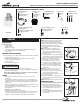

Instruction Manual/Instrucciones
Questions?/¿Preguntas? 1-800-334-6871 ConsumerProducts@cooperlighting.com
1
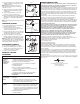
MOUNTING YOUR FIXTURE
NOTE: This fixture is intended to be conduit connected
to a properly installed and properly grounded metal
weatherproof junction box (not included). All conduit
connectors, conduit, and junction boxes (sold separately)
should be UL Listed suitable for wet locations.
1. Using the pattern on the box, mark and drill holes
for mounting.
NOTE: Mount this fixture in an upright position.
2. Install the two bottom mounting screws (E) first,
leaving enough room between the mounting
screws and the mounting surface to accommodate
mounting the fixture.
3. Screw the top mounting screw (E) into the predrilled
hole and back the screw out. This will leave the hole
threaded and make installation of the fixture easier.
4. Remove access cover (D) from parts bag.
5. Install the first conduit connector and conduit
(sold separately) into the access cover (D).
6. Feed supply wires into conduit and make wiring
connections as described in “Wiring Your Fixture”.
7. Attach access cover (D) to the light fixture (A)
using the two access cover mounting screws (F)
provided (Fig. 1).
NOTE: Make sure all wiring is placed into the arm
prior to tightening the access cover screws (F).
8. Using the three mounting screws (E) provided, bolt
the housing (A) to the mounting surface.
9. Connect second conduit and conduit connector at
the junction box (Fig. 2).
10. Fasten lens assembly (B) to housing (A) using the
two lens assembly lock screws (G) and two washers
(H) provided (Fig. 3).
NOTE: Washers must be used to keep the lens in place.
wIRING YOUR FIXTURE
1. Turn off the power at the main fuse/breaker box.
2. Attach ground wire that is attached to fixture
housing (A) to the junction box earth ground wire.
3. Connect the black fixture wire to the black supply
wire (hot). Attach UL approved wire connector
(sold separately).
4. Connect the white fixture wire to the white supply
wire (neutral). Attach UL approved wire connector
(sold separately).
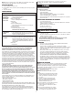
PACKAGING CONTENTS/CONTENIDO DEL PAQUETE
ITEMS REQUIRED
(Purchase separately)
• Phillips screwdriver
• Adjustable wrench
• Drill with 3/16 in. drill bit
• 1/2 in. diameter flexible conduit (if applicable, length depends on application)
• 1/2 in. watertight conduit connectors (if applicable)
• Wire connectors
IMPORTANT SAFETY INSTRUCTIONS
When using product, basic precautions should always be followed, including the following:
• Read and follow these instructions.
• Heed all warnings, including below warnings AND those included on product.
• Save these instructions and warnings.
• For outdoor use only.
• cULus LISTED for wet location use.
• Disconnect at fuse or circuit breaker before installing or servicing.
• Disconnect power and allow fixture to cool before changing bulb or handling fixture.
• Edges may cut. Handle with care.
Notice: Lamps contain mercury, dispose according to local, state, or federal laws.
For more information, visit: www.lamprecycle.org.
CAUTION
• Connect fixture to a 120 volt, 60 Hz power source. Any other connection voids
the warranty.
• Fixture should be installed by persons with experience in household wiring or by a
qualified electrician. The electrical system, and the method of electrically connecting
the fixture to it, must be in accordance with the National Electrical Code and local
building codes.
• Always use same wattage and type of bulb that was included with the fixture. Failure
to do so will void the warranty. See fixture for wattage.
• Upside down installation can result in overheating or accumulation of water in fixture.
Install right side up.
• MINIMUM 90° C SUPPLY CONDUCTORS.
• This device complies with Part 18 of the FCC Rules.
• This product may cause interference to radio equipment and should not be installed
near maritime safety communications equipment, ships at sea or other critical
navigation or communications equipment operating between 0.45-30 MHz.
AL6501FL
A. Fixture housing with
light sensor
Alojamiento del accesorio
con detector de luz
ENGLISH
E. (3) Mounting screws
(3) Tornillos de montaje
B. One-piece lens
assembly
Ensamblado del
lente de una
sola pieza
C. 65 watt fluorescent bulb
Bombilla fluorescente
de 65 vatios
D. Access cover
Cubierta de
acceso
G. (2) Lens assembly lock screws
(2) Tornillos de fijación del
ensamblado del lente
F. (2) Access cover mounting screws
(attached to fixture)
(2) Tornillos de la cubierta de acceso
(conectado al accesorio)
H. (2) Washers
(2) Arandelas
Fig. 2
Conduit
Junction
box
Conduit
connector
A
Fig. 1
F
F
D
A
Fig. 3
A
B
G
H
WARNING