
Installation Guide


6.5
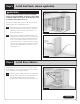
Fasten the cabinet to the wall with #10 x 2
1
⁄2” wall
attachment (pan head) screws.
6.6
If there is a blind corner cabinet, seal the opening with the
1
⁄8” panel packed inside the cabinet, as previously described
in the wall cabinet installation section.
6.7
Next, shim the adjacent cabinet into position and check for
level and plumb. Once again, clamp the face frames when
they are perfectly flush, drill pilot holes and join the two
cabinets with screws as previously described.
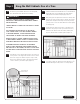
6.8
Continue this process until all cabinets are in place, making
sure that each cabinet is resting at the line on the wall,
level and plumb with each adjacent cabinet. Also make
sure to screw cabinets to each other at the face frames
before screwing to the wall. (Figure 18)
6.9
The final step is adding fillers between the last cabinet and
the wall. Reference the layout provided by your designer for
location and dimension.
NOTE: YOU MAY NEED TO CREATE CUTOUTS FOR PLUMBING
AND ELECTRICAL JUNCTION BOXES. BE SURE TO MEASURE
AND MARK ACCURATELY. CUT HOLES FROM THE BACK OF
THE CABINET BEFORE MOUNTING TO THE WALL.
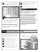
6.2
Start with the corner cabinet (if there is one) and place it
in position where it is to be mounted. When using a blind
base cabinet, make sure the cabinet is pulled out from the
corner the appropriate distance as called for in your kitchen
plan. (Figure 17)
NOTE: A BLIND BASE CABINET FILLS THE VOID OF THE
CORNER WITH USABLE STORAGE. THE DOOR COMES PRE-
MOUNTED ON THE LEFT SIDE, BUT CAN BE MOVED TO THE
RIGHT DEPENDING ON YOUR DESIGN (SEE DIAGRAM B).
6.3
Make sure your cabinet reaches the 34
1
⁄2” high level line
you drew on the wall. If not, you may have to shim into
position or use scrap to raise it to the proper level. If the
cabinet is tilting backward, shims at the back edge will
help. If it’s tilting forward, use the pry bar under the front
to adjust and then shim.
6.4
Measure from the corner to the first stud mark and transfer
the measurement to the inside of the cabinet to be
installed. Repeat this step for each and every stud. Now
drill
7
⁄32” mounting holes through the center of the hanging
rail inside of the cabinet.
Figure 18
Shim as required
Shim as
required
Clamp face
frames together
Frame
attachment
screws
3
⁄32" pilot holes
Hardwood hanging rail
Check for level
Check for plumb
Wall stud
locations
Wall attachment
screws
DIAGRAM B
Adjacent
base cabinet
Blind base cabinet
Filler –refer to your layout
for the appropriate filler
width and distance to
pull the cabinet from
the wall.
Figure 17
Shim as required
Check for level
Filler
Shim
as required
Check for plumb
Highest point
level line
Wall stud
locations
Wall stud location
10