
Installation Guide
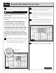
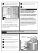
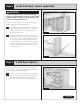


DIAGRAM F
MOLDING CUTS
90º ANGLES: CUT MOLDING AT 45º ANGLE
135º ANGLES: CUT MOLDING AT 22.5º ANGLE
158º ANGLES: CUT MOLDING AT AN 11º ANGLE
DIAGRAM G
8.1
Once all cabinets are hung, leveled and screws are tightened,
it is helpful to sweep out or vacuum any debris or sawdust.
8.2
Install shelves by placing the shelf supports into the holes
on both sides of the cabinet, push in completely and turn
until the flat side rests upward and place the shelves into
position. On wide cabinets, you will also need to insert a
shelf rest on the back wall and front stile of the cabinet
for added stability using the kit enclosed with the cabinet.
(Figure 22)
8.3
Install any interior convenience kits, such as tray dividers, rolling
shelves, wastebaskets, etc. See instructions with each kit.
8.4
Install the toe kick overlay along the bottom of the base
cabinets. Simply measure a continuous run of base cabinets
and cut a piece of toe kick to that length and adhere with
adhesive caulk and pin nails spaced about 24 inches apart.
8.5
Reattach doors by replacing the screws through the hinges.
8.6
Insert drawers into the glides. (See Appendix for drawer
install technique if necessary.)
8.7
Remove the wall support rail and fill the screw holes with
spackling. The wall is now ready for your backsplash material.
Step 8 Final Assembly and Cleanup
Figure 22
Rear shelf
support screw
Shelf support
dowel
Stile
Front shelf
support
158º
(outside)
135º
(outside)
135º (outside)
BEA24
BEA12
BASE CABINETS ONLY
135º (outside)
135º
(inside)
90º
(outside)
90º (inside)
WER, BER, BSS
& CAR
Corner Wall &
Corner Base
WEA
WALL AND BASE CABINETS
13