
Installation Guide


Step 4 Install Fillers (where applicable)
3.7
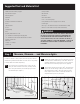
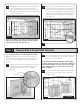
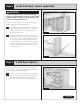
If there is a blind corner cabinet, the opening should be sealed
at this point with the
1
⁄8” panel packed inside the cabinet.
Pre-drill for small finishing nails or use a pin nailer. (Figure 12)
3.8
Continue along the walls until all cabinets are in place. If a
tall or utility cabinet is part of your plan, it should be added
at this point. Once again, shim for proper height and to
align so that it is perfectly plumb with the adjacent wall
cabinet. Once face frames are flush, clamp, drill and screw
together as previously described.
NOTE: AT THIS POINT, YOU MAY WANT TO SET THE TALL
CABINET INTO POSITION TO BE SURE IT FITS PROPERLY.
NOTE: REFER TO SPECIFIC INSTRUCTIONS THAT COME WITH
SPECIALTY TALL CABINETS.
Fillers may be necessary when installing cabinets. They help allow
for odd dimensions between a run of cabinets and the wall. They
also allow clearance for doors and drawers to operate properly
when turning a corner with a blind corner cabinet. Fillers and
valances often have to be trimmed to fit.
4.1
Measure the area requiring a filler piece. Carefully trim the
filler piece to the appropriate width with a saw.
4.2
Clamp the filler in place and once again, drill a pilot hole on the
hinge side of the face frame and into the filler.
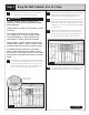
4.3
Fasten the filler to the cabinet with #8 x 2
1
⁄2” frame
attachment (trim head) screws. (Figure 13)
4.4
If using a blind corner base, secure the other end of the
filler through the inside of the cabinet with the same pilot
hole and frame attachment screw technique.
Figure 13
Frame
attachment
screw
3
/
32
” pilot hole
Filler
Hinge mounting
screw hole
Clamp
filler panel to
face frame
Install backer for fillers
greater than 3” to secure
the filler to the wall.
3.9
Once all cabinets are properly shimmed and properly
positioned, finish tightening the screws to secure the
cabinets to the walls.
3.10
Remove the support rails and spackle screw holes if
needed.
WARNING
TO AVOID RISK OF DRIVING SCREWS BEYOND THE
CABINET FACE, CARE MUST BE TAKEN TO PREVENT OVER
TIGHTENING OF THE SCREWS AND DESTROYING THE
INTEGRITY OF THE HANGING STRIP.
TO REDUCE THE RISK OF SERIOUS INJURY OR DAMAGE FROM
A LOOSE OR FALLING CABINET, WALL CABINETS GREATER
THAN 12” IN DEPTH OR LARGER THAN 24” IN WIDTH MUST
NOT BE INSTALLED AND/OR USED AS SINGLE, STAND-
ALONE CABINETS WITHOUT TAKING EXTRA PRECAUTIONS
TO FULLY AND SAFELY SECURE THE CABINET TO THE
WALL. ADDITIONAL MOUNTING SUPPORT INTO A CEILING,
BULKHEAD, OR SIDE WALL(S) IS ALSO RECOMMENDED WHEN
POSSIBLE. WHEN THIS IS NOT POSSIBLE, THEN ADDITIONAL
SUPPORT MUST BE PROVIDED EITHER ABOVE OR BELOW
THE CABINET TO SUPPORT WEIGHT AT A POINT AT LEAST
12” FROM THE WALL. THIS CAN BE DONE THROUGH ANGLE
BRACKETS/BRACING, SHELVING, AND/OR ADDITIONAL
CABINETS AS A STAND.
Figure 12
T-brace
Temporary
support rails
Blind wall cabinet
Provided
1
⁄8" panel
Wall stud locations
8