welcoming • sophisticated • inspiring ITEM #2416659 ELECTRIC FIREPLACE TV STAND ® allen + roth is a registered trademark of LF, LLC. All rights reserved. MODEL #2360FM-24-259 Français p. 24 Español p. 47 ATTACH YOUR RECEIPT HERE Serial Number__________________ Purchase Date__________________ Questions, problems, missing parts? Before returning to your retailer, call our customer service department at 1-866-439-9800, 8 a.m. - 8 p.m., EST, Monday - Sunday.
TABLE OF CONTENTS Package Contents................................................................................................................................ 3 Hardware Contents.............................................................................................................................. 4 Safety Information................................................................................................................................ 4 Preparation.........................................
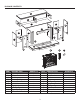
PACKAGE CONTENTS A C J B B D L E L I G M H M P F R O K Q PART A B C D E F G H I J DESCRIPTION Top Corner Panel Partition Center Shelf Center Front Panel Left Wall Right Wall Left Side Panel Right Side Panel Center Back Panel N PART K L M N O P Q R S T QUANTITY 1 2 1 1 1 1 1 1 1 1 3 S DESCRIPTION Base Back Panel Shelf Insert Left Front Panel Right Front Panel Left Front Door Right Front Door Remote Control Battery T QUANTITY 1 2 2 1 1 1 1 1 1 2
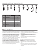
HARDWARE CONTENTS (NOT SHOWN ACTUAL SIZE) AA PART AA BB CC DD EE FF GG HH II BB CC DESCRIPTION Wooden Dowel Short Screw Locknut Connecting Rod Long Screw Back Panel Screws Shelf Pin Door Pull Touch-Up Pen DD EE FF GG HH II QUANTITY 38 2 28 28 8 38 8 2 1 SAFETY INFORMATION Please read and understand this entire manual before • Reorient or relocate the receiving antenna attempting to assemble, operate or install the product.
SAFETY INFORMATION (CONT'D) • This appliance has hot and arcing or sparking parts inside. DO NOT use it in areas where gasoline, paint or flammable vapors or liquids are used or stored. This fireplace should not be used as a drying rack for clothing. Christmas stockings or This Class B digital apparatus complies with Canadian decorations should not be hung in the area of it. ICES-003. • Use this appliance only as described in the manual.
SAFETY INFORMATION (CONT'D) • To prevent a possible fire, DO NOT block air intakes or exhaust in any manner. DO NOT use on soft surfaces, like a bed, where opening may become blocked. • The heaters MUST NOT be located immediately below a socket-outlet. • ALWAYS plug heaters directly into a wall outlet / receptacle. NEVER use with an extension cord or re-loadable power tap (outlet / power strip). • DO NOT slide insert on top of wood to avoid scratching wood surface.
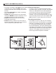
PREPARATION Before beginning assembly of product, make Estimated Assembly Time: 50 minutes sure all parts are present. Compare parts with package contents list and hardware contents list. Tools Required for Assembly (not included): If any part is missing or damaged, do not attempt Phillips screwdriver to assemble the product. ASSEMBLY INSTRUCTIONS 1. Set center front panel (E) down on a non-scratch surface. Insert six wooden dowels (AA) into holes on left and right sides of center front panel (E).
ASSEMBLY INSTRUCTIONS (CONT’D) 3. Insert four wooden dowels (AA) into the holes on the back of the left front panel (O) and right front panel (P). Attach the left side panel (H) to the left front panel (O), secure with screwing three locknuts (CC) by Phillips screwdriver. 3 H CC Repeat for the right side panel (I). I Hardware Used AA Wooden Dowel x4 CC Locknut x6 1 1 AA O P 2 4.
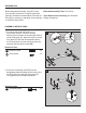
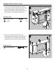
ASSEMBLY INSTRUCTIONS (CONT’D) 5. Insert two wooden dowels (AA) into outer holes on right side of base (K). Align and attach right wall (G), securing from underneath with two long screws (EE). 5 G Repeat for left wall (F). F Hardware Used 1 AA Wooden Dowel x4 EE Long Screw x4 AA EE 2 6. Screw ten connecting rods (DD) into the designated plastic bushings on the back of the center shelf (D).
ASSEMBLY INSTRUCTIONS (CONT’D) 7. Insert two wooden dowels (AA) into the top outer holes on both left wall (F), left side panel (H), right side panel (I) and right wall (G). Attach center shelf (D), secure with screwing ten locknuts (CC) by Phillips screwdriver. 7 CC 1 D AA I 1 G Hardware Used AA Wooden Dowel x8 CC Locknut x 10 F H 2 8.
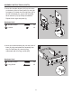
ASSEMBLY INSTRUCTIONS (CONT’D) 9. Insert two wooden dowels (AA) into holes on left side of center shelf (D). Attach corner panel (B), secure with screwing four locknuts (CC) by Phillips screwdriver. Repeat for remaining corner panel (B). 9 CC B 1 AA B D 1 Hardware Used AA Wooden Dowel x4 CC Locknut x4 CC 2 10. Insert one wooden dowels (AA) into holes on the middle of center shelf (D). Attach partition (C), secure with screwing two locknuts (CC) by Phillips screwdriver.
ASSEMBLY INSTRUCTIONS (CONT’D) 11. Screw six connecting rods (DD) into designated plastic bushings on the back of the top (A). Fully tighten with a Phillips screwdriver. 11 DD Hardware Used DD Connecting Rod A x6 DD 12. Insert wooden dowels (AA) into the top outer holes of corner panel (B) and partition (C). Attach top (A), secure with screwing six locknuts (CC) by Phillips screwdriver.
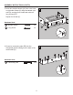
ASSEMBLY INSTRUCTIONS (CONT’D) 13. From behind the assembly, attach back panel (L) to shelving areas using back panel screws (FF). 13 Repeat for remaining back panel (L). FF Hardware Used FF Back Panel Screw L x 20 14. From behind the assembly, attach center back panel (J) to shelving areas using back panel screws (FF).
ASSEMBLY INSTRUCTIONS (CONT’D) 15. Insert shelf pins (GG) at desired height, ensuring they are level. Place shelf (M) on top of shelf pins (GG). 15 Repeat for remaining the shelf (M). Hardware Used GG Shelf Pin 2 x8 2 M M 1 GG 16. Place door pull (HH) into predrilled hole on right door, securing with two door pull bolt. 16 Repeat for remaining door pull (HH).
ASSEMBLY INSTRUCTIONS (CONT’D) 17. Install the doors I. Loosen the screws on the hinge arms and plates pre-attached on the walls (F and G). II. Pick up left front door (Q) and attach it to left wall (F) by engaging both door hinges simultaneously. Please follow the steps below to combine the door hinges together. i. Extend both hinge arms on the left front door (Q) to open position. ii. Insert the “J” hooks beneath the hinge arms into the lugs on mounting plates pre-attached on left wall (F). iii.
ASSEMBLY INSTRUCTIONS (CONT’D) 19. From behind the assembly, remove the preassembled insert brackets from the middle area. Save brackets and screws for future use. 19 2 2 1 Note: Before proceeding to the next step, with the help of another person, move the mantel close to the final desired location. 20 20. With the help of another person, position insert (N) into middle opening of mantel assembly. Note: DO NOT plug insert (N) into power outlet yet.
ASSEMBLY INSTRUCTIONS (CONT’D) 21. Re-attach insert brackets with previously removed screws to secure insert (N). 21 Assembly is now complete. With the help of another person, move the assembly to the final desired location. Once in final position you may plug the insert (N) into the power outlet. 1 1 N 2 NOTE: Use the pre-assembled levelers on the base of the fireplace to level the unit. Twist the levelers counter-clockwise to increase the height, twist the clockwise to decrease the height.
OPERATING INSTRUCTIONS Control Panel Remote Control To use the remote control, first insert two AAA batteries (included) into the remote control. Ensure the polarities of the batteries match the inside of the battery compartment. M Note: The control panel is a touch screen. It will appear black. Touch the control panel once to “wake up” the controls. This will cause the controls to light up. Whichever icon you touch will display its last setting when you do this.
OPERATING INSTRUCTIONS (CONT’D) Timer Function • Press the TIMER ICON to set the countdown for the unit’s main power. • If the unit is powered OFF, you can press the TIMER ICON to power ON the unit. The ember bed will glow at the lowest brightness setting unless a different setting was saved in the memory. • Press the TIMER ICON again to scroll through the timer settings, which are: 30, 1h, 2h, 3h, 4h, 5h, 6h, 7h, 8h, 9h, OFF.
CARE AND MAINTENANCE • Make sure the unit is turned OFF, unplugged and the heating elements of heater are cool whenever you are cleaning the heater or fireplace. • Clean the metal trim using a water-dampened soft, clean cloth. DO NOT use brass polish or household cleaners as these products will damage the metal trim. • The motors used on the fan and the flame generator assembly are pre-lubricated for extended bearing life and require no further lubrication.
TROUBLESHOOTING PROBLEM POSSIBLE CAUSE Error E1 displayed on The overheat sensor has control panel. been engaged. CORRECTIVE ACTION Unplug unit, wait 15-20 minutes, then the sensor will reset itself. Plug the unit back in and turn on the heater. If the problem persists, call customer service. Note: The other functions will work normally excluding the heater. Until the problem is solved, the error will only appear/sound when the heater button is pressed.
ONE-YEAR LIMITED WARRANTY The manufacturer warrants that your new electric fireplace is free from manufacturing and material defects for a period of one year from date of purchase, subject to the following conditions and limitations. Install and operate this electric fireplace in accordance with the installation and operating instructions furnished with the product at all times. Any unauthorized repair, alteration, willful abuse, accident, or misuse of the product shall nullify this warranty.
REPLACEMENT PARTS LIST For replacement parts, call our customer service department at 1-866-439-9800, 8 a.m. - 8 p.m., EST, Monday - Sunday.