welcoming • sophisticated • inspiring ANS Z21.97/CSA 2.41-2014 Outdoor Decorative Gas Appliances ITEM #0871274 allen + roth® is a registered trademark of LF, LLC. All Rights Reserved. BAR TABLE MODEL #FG-BKV32CHFP ATTACH YOUR RECEIPT HERE Serial Number Purchase Date Español p. 18 Questions, problems, missing parts? Before returning to your retailer, call our customer service department at 1-866-439-9800, 8 a.m. - 8 p.m., EST, Monday - Friday.
TABLE OF CONTENTS SAFETY INFORMATION ................................................................................................................ 2 PACKAGE CONTENTS .................................................................................................................. 5 HARDWARE CONTENTS............................................................................................................... 6 PREPARATION ...................................................................................
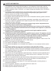
SAFETY INFORMATION 1. The installation must conform with local codes or, in the absence of local codes, with the 2. 3. 4. 5. 6. 7. 8. 9. 10. 11. 12. 13. 14. 15. 16. 17. 18. 19. 20. 21. 22. 23. National Fuel Gas Code, ANSI Z223.1●NFPA 54; National Fuel Gas Code; Natural Gas and Propane Installation Code, CSA B149.1; or Propane Storage and Handling Code, CSA B149.2, as applicable.
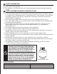
SAFETY INFORMATION 24. Never leave a fire unattended. 25. The appliance is hot during and after use. Always allow ample cooling time before touching or moving. SAFETY INFORMATION ABOUT PROPANE (LP) GAS 1. The LP-gas supply cylinder to be used must be constructed and marked in accordance with the U.S. Deparment of Transportation (D.O.T.) Specifications for LP-Gas Cylinders, or the Standard for Cylinders, Spheres and Tubes for Transportation of Dangerous Goods and Commission, CAN/CSA-B339, as applicable. 2.
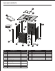
PACKAGE CONTENTS P A N D H C I J Q L E G B PART A B C D E F G H I J K DESCRIPTION Table top assembly Door Left panel Back panel Right panel Front-right leg Front-left leg Back-left leg Back-right leg Upper beam Bottom beam K O F QUANTITY PART 1 1 1 1 1 1 1 1 1 1 1 L M N O P Q 5 M DESCRIPTION Gas cylinder support Foot glider Weather cover Door handle Lid Lava rocks (6.6 lb.
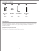
HARDWARE CONTENTS AA BB CC DD M6 x 15 mm Bolt M6 Washer Hex screwdriver M4 x 25 mm Bolt Qty. 30 Qty. 30 Qty. 1 Qty. 1 PREPARATION Before beginning assembly of product, make sure all parts are present. Compare parts with package contents list and hardware contents list. If any part is missing or damaged, do not attempt to assemble the product. Estimated Assembly Time: 25 minutes Tools Required for Assembly (not included): Phillips screwdriver.
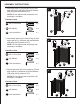
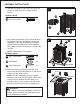
ASSEMBLY INSTRUCTIONS 1. Attach left panel (C) to front-left leg (G) and back-left leg (H) with bolts (AA) and washers (BB) using hex screwdriver (CC). 1 NOTE: Do not tighten bolts completely until assembly is complete. CC AA C BB Hardware Used AA M6 x 15 mm Bolt x4 BB M6 Washer x4 CC Hex screwdriver x1 G 2. Attach back panel (D) to back-left leg (H) and back-right leg (I) with bolts (AA) and washers (BB) using hex screwdriver (CC).
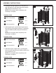
ASSEMBLY INSTRUCTIONS 4. Attach gas cylinder support (L) to left panel (C) and right panel (E) with bolts (AA) and washers (BB) using hex screwdriver (CC). 4 CC BB AA NOTE: Do not tighten bolts completely until assembly is complete. Hardware Used AA M6 x 15 mm Bolt x4 BB M6 Washer x4 CC Hex screwdriver C E L x1 5. Attach upper beam (J) and bottom beam (K) to front-left leg (G) and front-right leg (F) with bolts (AA) and washers (BB) using hex screwdriver (CC).
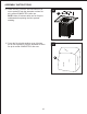
ASSEMBLY INSTRUCTIONS 7. Attach door handle (O) with bolt (DD), then use Phillips screwdriver (not included) to screw tightly. 7 Hardware Used DD M4 x 25 mm Bolt DD x1 O O 8. Place table top assembly (A) on a non-abrasive flat surface to prevent scratching. Attach base assembly to table top assembly (A) with bolts (AA) and washers (BB) using hex screwdriver (CC). Make sure the control panel is towards the door (B). 8 AA CC BB NOTE: Tighten all bolts completely.
ASSEMBLY INSTRUCTIONS 10. Place the lid (P) onto the fire bowl when not in use to protect it from the elements or when fire pit is cooled COMPLETELY after use. 10 P NOTE: Allow 30 minutes after use for fire pit to cooldown before placing the lid to prevent scalding. 11. Cover the fire pit with weather cover (N) when not in use to protect it from the elements or when fire pit is cooled COMPLETELY after use.
OPERATING INSTRUCTIONS GAS CYLINDER INSTALLATIONS 1. Open the door (B) and place the gas cylinder (not included) into gas cylinder support (L). 1 B L 2. Connect the regulator. Screw the black handle clockwise to tighten, turn the black handle counterclockwise to remove. The hose must point down. The knob on the control panel is turned all the way to the “OFF” position when the fire pit is NOT in use. 2 3.
OPERATING INSTRUCTIONS CHECKING FOR LEAKS 1. Make 2 - 3 oz. of leak solution by mixing one part liquid dishwashing detergent and three parts water. 2. Apply several drops of solution where the cylinder attaches to the regulator and inspect the solution at the connection looking for bubbles. If NO bubbles appear, the connection is secure. If bubbles appear, the connection has a leak. Disconnect the regulator and reconnect, then perform another leak check.
OPERATING INSTRUCTIONS BATTERY INSTALLATION Make sure the control knob is in the “OFF” position. Unscrew the push button cap on the ignitor module located on the control panel to access the battery compartment. The ignitor module requires one AAA size battery. BATTERY IS NOT INCLUDED. CAUTION Please observe proper polarity and use the correct battery type when placing or replacing the battery. Improper installation could result in ignition failure.
OPERATING INSTRUCTION CHECKING FOR FLAMES Observe flame height when lit. The burner will display blue and yellow flames. These flames should be a blue/yellow color between 1 - 2 in. height. These flames should not be yellow or produce thick smoke. This would indicate an obstruction of airflow through the burners. The flames should be blue with straight yellow tops. Good Bad Yellow Yellow Light Blue Light Blue Blue Blue CARE AND MAINTENANCE Use warm soapy water for cleaning.
TROUBLESHOOTING PROBLEM POSSIBLE CAUSE CORRECTIVE ACTION 1. The gas cylinder is frosted over. 2. The openings are blocked. 3. The control knob is not in the “ON” The burner will not position. ignite. 4. There may be too many lava rocks covering the burner bowl or small pieces may be blocking the burner ports. The burner flame is too low. 1. The gas pressure is low. 2. The cylinder is less than 1/4 full. 1. Wait until gas cylinder warms up and becomes unfrosted. 2. Clear the blockage. 3.
WARRANTY Firepits Burner, steel fire pit bowl, all mechanical parts and fittings to control panel and burner assembly, and all fire pit tops that are not cast aluminum are warranted for a period of one (1) year from original date of purchase, against defects in material and or workmanship. Rust is not covered. Frames Frames are warranted to be free from defects in materials and workmanship for a period of three (3) years.
REPLACEMENT PARTS LIST For replacement, call our customer service department at 1-866-439-9800, 8 a.m. - 8 p.m., EST, Monday - Friday.
welcoming • sophisticated • inspiring ANS Z21.97/CSA 2.41-2014 #08 # ¿Preguntas, problemas, piezas faltantes? Antes de volver a la tienda, llame a nuestro 66-439-9800 de lunes a viernes de 8 a.m. a 8pm., hora estándar del Este.
ÍNDICE INFORMACIÓN DE SEGURIDAD ................................................................................................... 20 CONTENIDO DEL PAQUETE ......................................................................................................... 22 ADITAMENTOS .............................................................................................................................. 23 PREPARACIÓN.............................................................................................
INFORMACIÓN DE SEGURIDAD 1. La instalación debe cumplir con los códigos locales o, de no haberlos, con el Código Nacional de Gas, ANSI Z223.1●NFPA 54; el Código Nacional de Gas; el Código lde Instalación de Gas Natural y Propano, CSA B149.1; o el Código de Manipulación y Almacenamiento de Propano, CSA B149.2, según corresponda. 2.
INFORMACIÓN DE SEGURIDAD 24. 25. INFORMACIÓN DE SEGURIDAD SOBRE EL GAS PROPANO (PL) 1. 2. 3. 4. 5. 6. 7. 8. 9. 10. 11. WARNING: FUELS USED IN LIQUEFIED PROPANE GAS APPLIANCES, AND THE PRODUCTS OF COMBUSTION OF SUCH FUELS, CAN EXPOSE YOU TO CHEMICALS INCLUDING BENZENE, WHICH IS KNOWN TO THE STATE OF CALIFORNIA TO CAUSE CANCER AND CAUSE BIRTH DEFECTS OR OTHER REPRODUCTIVE HARM. For more information go to: www.P65Warnings.ca.gov.
CONTENIDO DEL PAQUETE P A N D H C I J Q L E G B Pieza A B C D E F G H I J K Descripción K O Cantidad 1 1 1 1 1 1 1 1 1 1 1 22 F M Pieza Descripción Cantidad L M N O P Q Soporte del cilindro de gas Tapa 3 1 4 1 1 1 1
ADITAMENTOS AA BB Perno M6 x 15 mm Arandela M6 Cant. 30 Cant. 30 CC Destornillador hexagonal Cant. 1 DD Perno M4 x 25 mm Cant.1 PREPARACIÓN Antes de comenzar a ensamblar el producto, asegúrese de tener todas las piezas. Compare las piezas con la lista del contenido del paquete y la lista del contenido de aditamentos. No intente ensamblar el producto si falta alguna pieza o si estas están dañadas. Tiempo estimado de ensamblaje: 25 minutos.
INSTRUCCIONES DE ENSAMBLAJE 1. Fije el panel izquierdo (C) a la pata izquierda frontal (G) y a la pata izquierda posterior (H) con pernos (AA) y arandelas 1 NOTA: no apriete los pernos por completo hasta finalizar el ensamblaje. CC AA C BB Aditamentos utilizados AA Perno M6 x 15 mm x4 BB Arandela M6 x4 CC Destornillador x1 hexagonal G 2.
INSTRUCCIONES DE ENSAMBLAJE 4. Fije el soporte del cilindro de gas (L) al panel izquierdo (C) y al panel derecho (E) con pernos (AA) y arandelas (BB) usando el destornillador hexagonal (CC). NOTA: no apriete los pernos por completo hasta finalizar el ensamblaje. 4 CC BB AA Aditamentos utilizados AA Perno M6 x 15 mm x4 BB Arandela M6 x4 CC Destornillador x1 hexagonal C E L 5.
7. 7 DD DD x1 O O 8. 8 AA BB Asegúrese de que el panel de control esté orientado hacia la puerta (B). AA x4 BB x4 CC x1 A B 9. panel de control 9 3 Q ADVERTENCIA pueden tragar.
INSTRUCCIONES DE ENSAMBLAJE 10. 10 P 11. Cubra el fogón con la cubierta para la intemperie (N) cuando no esté en uso para protegerlo de los factores climáticos o cuando se haya enfriado POR COMPLETO después de haberlo usado.
INSTRUCCIONES DE FUNCIONAMIENTO INSTALACIÓN DEL CILINDRO DE GAS 1. Abra la puerta (B) y coloque el cilindro de gas (no seincluye) en el soporte del cilindro de gas (L). 1 B L 2. Conecte el regulador. Gire la manija negra en dirección de las manecillas del reloj para apretarla; gire la manija negra en dirección contraria a las manecillas del reloj para retirarla. La manguera debe apuntar hacia abajo.
INSTRUCCIONES DE FUNCIONAMIENTO BÚSQUEDA DE FUGAS 1. Prepare entre 59,14 ml y 88,72 ml de solución para detección de fugas mezclando una parte de detergente líquido para platos con tres partes de agua. 2. Aplique varias gotas de solución donde el cilindro se fija al regulador y revise si se forman burbujas en el área de las conexiones. Si NO se forman burbujas, la conexión está segura. Si se forman burbujas, la conexión tiene una fuga. Desconecte el regulador y vuelva a conectar.
INSTRUCCIONES DE FUNCIONAMIENTO INSTALACIÓN DE LAS BATERÍAS Asegúrese de que la perilla de control esté en la posición "OFF" (apagado). Desatornille la tapa del botón en el módulo del encendedor que se encuentra en el panel de control para acceder al compartimiento de las baterías. El módulo del encendedor necesita una batería tamaño AAA. NO INCLUYE LA BATERÍA. PRECAUCIÓN Respete la polaridad adecuada y use el tipo de batería correcto cuando instale o reemplace la batería.
INSTRUCCIONES DE FUNCIONAMIENTO VERIFICACIÓN DE LLAMAS Observe la altura de las llamas. El quemador producirá llamas azules y amarillas. Estas llamas deben ser de color azul con amarillo y deben medir entre 2,54 cm y 5,08 cm de altura. Las llamas no deben ser amarillas ni deben producir humo espeso. Si sucede esto, indicaría una obstrucción del flujo de aire a través de los quemadores. Las llamas deben ser de color azul con puntas amarillas rectas.
SOLUCIÓN DE PROBLEMAS PROBLEMA El quemador no se enciende. La llama del quemador es demasiado baja. Hay acumulación de carbono o humo espeso y negro. CAUSA POSIBLE ACCIÓN CORRECTIVA 1.El cilindro de gas está cubierto de escarcha. 2.Las aberturas están bloqueadas. 3.La perilla de control no está en la posición "ON" (encendido). 4.Podría haber demasiadas rocas de lava cubriendo la fuente del quemador o pequeñas piezas bloqueando los puertos del quemador. 1.
GARANTÍA Fogones El quemador, la fuente del fogón de acero, todas las piezas mecánicas y los conectores al panel de control y al ensamble del quemador y todas las cubiertas del fogón que no son de aluminio fundido están garantizadas durante un (1) año a partir de la fecha original de compra, contra defectos en el material o la mano de obra.La garantía no cubre el óxido. Estructuras Las estructuras están garantizadas contra defectos en los materiales y la mano de obra durante tres (3) años.
LISTA DE PIEZAS DE REPUESTO Para obtener piezas de repuesto, llame a nuestro Departamento de Servicio al Cliente al PART # del Este. 1-866-439-9800 de lunes a viernesESCRIPTION de 8 a.m. a 8pm.