
Installation Guide
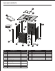

ASSEMBLY INSTRUCTIONS
8
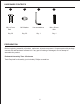
Hardware Used
AA
x 8
M6 x 15 mm Bolt
BB
x 8
M6 Washer
CC
x 1
Hex screwdriver
5
CC
AA
BB
G
F
K
J
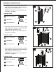
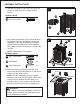
Attach upper beam (J) and bottom beam (K) to
front-left leg (G) and front-right leg (F) with bolts
(AA) and washers (BB) using hex screwdriver
(CC).
NOTE: Do not tighten bolts completely until
assembly is complete.
5.
Hardware Used
AA
x 2
M6 x 15 mm Bolt
BB
x 2
M6 Washer
CC
x 1
Hex screwdriver
6
CC
AA
BB
B
K
J
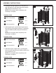
Attach door (B) to upper beam (J) and bottom
beam (K) with bolts (AA) and washers (BB) using
hex screwdriver (CC).
NOTE: Do not tighten bolts completely until
assembly is complete.
6.
Hardware Used
AA
x 4
M6 x 15 mm Bolt
BB
x 4
M6 Washer
CC
x 1
Hex screwdriver
4
E
L
C
CC
AA
BB
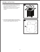
Attach gas cylinder support (L) to left panel (C)
and right panel (E) with bolts (AA) and washers
(BB) using hex screwdriver (CC).
NOTE: Do not tighten bolts completely until
assembly is complete.
4.