
Assembly Instructions

K
3
2
TABLE OF CONTENTS
Camlock System Operation............................................................................................... 2
Package Contents............................................................................................................... 3
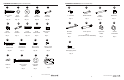
Hardware Contents...............................................................................................................4
Safety Information............................................................................................................... 6
Preparation ......................................................................................................................... 6
Assembly Instructions......................................................................................................... 7
Care and Maintenance ....................................................................................................... 17
Troubleshooting................................................................................................................... 17
Warranty.............................................................................................................................. 19
Replacement Parts List ...................................................................................................... 19
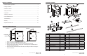
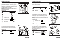
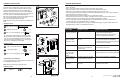
PACKAGE CONTENTS
K
PART DESCRIPTION QUANTITY
A Hutch Panel Left 1
B Hutch Panel Right 1
C Hutch Panel Top 1
D Hutch Panel Back 1
E Front Curved Stretcher 1
F Front Straight Stretcher 1
G Adjustable Shelf 1
H Base Panel Left 1
I Base Panel Right 1
J Base Panel Top 1
K Base Panel Back 1
L Base Panel Bottom 1
M Partition Panel 2
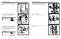
PART DESCRIPTION QUANTITY
N Shoe Shelf 2
O Wall Hanging Cleat 2
P Drawer Front 1
Q Drawer Panel Left 1
R Drawer Panel Right 1
S Drawer Back 1
T Drawer Bottom 1
U Slide 2
V Long Shelf 2
W Installation Template
1
X 22 mm Metal Pole 3
Y
25 mm Metal Pole 3
F
A
I
H
G
D
C
B
E
J
L
M
N
O
S
R
Q
T
U
P
V
W
Lowes.com/allenandroth Lowes.com/allenandroth
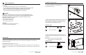
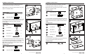
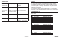
CAM LOCK SYSTEM OPERATION
1. Screw cam bolts into the predrilled small holes on panel.
2. Insert cam lock into predrilled large hole on panel.
3. Make sure the arrow on the cam lock is pointed toward the cam bolts.
4. Connect both panels together, making sure cam bolts goes into predrilled hole on
the end of panel with cam lock.
5. Once cam bolts is connected inside cam lock, take Phillips screwdriver and tighten
cam lock clockwise.
DETAIL A DETAIL B
THREADED
INSERT
LOCKED POSITION
PANELPANEL
Cam Bolts
CAM LOCK
X
Y