Installation Instructions for Stacked Washers and Dryers Inside...................................... Dimensions........................................................................ Before You Start................................................................ Installation......................................................................... 3 4 5 Installer Checklist ............................................
WARNING FOR YOUR SAFETY, the information in this manual must be followed to minimize the risk of fire or explosion or to prevent property damage, personal injury or death. W033 • Do not store or use gasoline or other flammable vapors and liquids in the vicinity of this or any other appliance. • WHAT TO DO IF YOU SMELL GAS: – Do not try to light any appliance. – Do not touch any electrical switch; do not use any phone in your building. – Clear the room, building or area of all occupants.
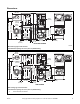
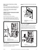
Dimensions 23.5 in. (59.7 cm) 8.0 in. (20.3 cm) 15.4 in. (39.1 cm) 1.5 in. (3.81 cm) 28 in. (71.1 cm) 2.0 in. (5.1 cm) *37.44 in. (95.1 cm) *13.1 in. (33.3 cm) *31.1 in. (79 cm) *29.6 in. (75.1 cm) *44.1 in. (112 cm) 24 in. (61 cm) *75.25 in. (191.1 cm) *54 in. (137.2 cm) *63 in. (160 cm) 5.25 in. (13.3 cm) 26.875 in. (68.3 cm) *14.6 in. (37.08 cm) ELECTRIC DRYERS SWD897N * With leveling legs turned into base. NOTE: Exhaust openings are 4 inch (10.2 cm) metal ducting. 23.5 in. (59.
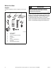
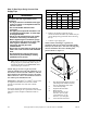
Before You Start WARNING Supplies For most installations, the basic supplies you will need are: Any disassembly requiring the use of tools must be performed by a suitably qualified service person. W299 1 3 2 NOTE: If the unit is delivered on a cold day (below freezing), or is stored in an unheated room or area during the cold months, do not attempt to operate it until the unit has had a chance to warm up. 5 6 4 7 NOTE: Some moisture in the wash drum is normal.
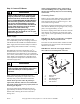
Installation Step 1: Position Unit Near Installation Area Move unit as close to the desired area of installation as possible. NOTE: For best performance and to minimize vibration or movement, install washer on a solid, sturdy and level floor. Some floors may need to be reinforced, especially on a second floor or over a basement. Do not install the washer on carpeting, soft tile, a platform or other weakly supported structures.
NOTE: Use of the dispenser drawer or unit doors as a handle in the transportation of the unit may cause damage to the dispenser or doors. Place unit in position on a solid, sturdy and level floor. Installing the unit on any type of carpeting, soft tile, a platform or other weakly supported structures is not recommended. Place a level on the cabinet top and check if the unit is level from side to side and front to back. NOTE: Level must rest on raised portion of top panel. Refer to Figure 3.
Step 3: Connect Fill Hoses NOTE: When installing in newly constructed or renovated buildings, it is very important to flush the lines since build-up may have occurred during construction. WARNING Under certain conditions, hydrogen gas may be produced in a hot water system that has not been used for two weeks or more. HYDROGEN GAS IS EXPLOSIVE.
IMPORTANT: Hoses and other natural rubber parts deteriorate after extended use. Hoses may develop cracks, blisters or material wear from the temperature and constant high pressure they are subject to. Risers Risers (or air cushions) may have to be installed if the pipes knock or pound when flow of water stops. The risers are more efficient when installed as close as possible to the water supply faucets (refer to Figure 7).
Step 4: Connect Drain Hose to Drain Receptacle NOTE: End of drain hose must not be below 24 in. (61 cm). Remove the drain hose from its shipping position on the rear of the washer by unhooking the hose from the retainer clamp and by removing the shipping tape. Install the drain hose into the drain receptacle (standpipe, wall or laundry tub) following the instructions below. 1 2 IMPORTANT: Drain receptacle must be capable of handling a minimum of 1-1/4 inch (32 cm) outside diameter drain hose.
Step 5: (Gas Dryer Only) Connect Gas Supply Pipe Natural Gas Altitude Adjustments Altitude WARNING To reduce the risk of gas leaks, fire or explosion: • The dryer must be connected to the type of gas as shown on nameplate located in the door recess. • Use a new flexible stainless steel connector. • Use pipe joint compound insoluble in L.P. (Liquefied Petroleum) Gas, or Teflon tape, on all pipe threads. • Purge air and sediment from gas supply line before connecting it to the dryer.
4. Tighten all connections securely. Turn on gas and check all pipe connections (internal & external) for gas leaks with a non-corrosive leak detection fluid. NOTE: The dryer and its appliance main gas valve must be disconnected from the gas supply piping system during any pressure testing of that system at test pressures in excess of 1/2 psi (3.45 kPa). Refer to Step 12 (Check Heat Source). L.P. (Liquefied Petroleum) Gas, 2500 Btu/ft3 (93.1 MJ/m3) service must be supplied at 10 ± 1.
Grounding Information • This dryer must be connected to a grounded metal, permanent wiring system; or an equipment-grounding conductor must be run with the circuit conductors and connected to the equipment-grounding terminal or lead on the dryer. • For model LTSA7A*N2989, only flexible metal conduit, rigid metal conduit or armored cable wiring systems are recommended.
Connecting Power Cord with Three-Wire Plug NOTE: Four-wire cord is required for mobile homes or where codes do not permit grounding through neutral. NOTE: The power cord is NOT supplied with the electric dryer. Type of power cord and gauge of wire must conform to local codes and instructions. POWER SUPPLY POWER SUPPLY 1 The method of wiring the dryer is optional and subject to local code requirements. 2 NOTE: Connect the dryer to the power supply with the MAXIMUM RATED VOLTAGE listed on the nameplate.
4. Use the three screws from the accessories bag to attach the power cord wires to the terminal block. Refer to Figure 15. 1 Connecting Power Cord with Four-Wire Plug NOTE: Four-wire cord is required for mobile homes or where codes do not permit grounding through neutral. 2 2 1 3 3 12 V. 0 ± A 1 .C 2 . 4 D286I “L1” Terminal Neutral Terminal “L2” Terminal 240 ± 12 V.A.C. 12 V. 0 ± A 1 .C 2 . Figure 15 0 V.A.C. 12 V. 0 ± A 1 .C 2 . 1 2 3 12 V. 0 ± A 1 .C 2 . 5. Tighten all screws firmly.
3. Remove ground screw and save for use in Step 5. Remove wire and use in Step 6. 5. Attach power cord ground (green) wire to rear bulkhead using ground screw removed in Step 3. 1 1 7 6 5 2 4 D697I D697I 1 Ground Screw 3 DRY1920N DRY1920N Figure 18 4. Use a strain relief and insert end of power cord through power supply hole. 1 2 3 4 5 6 7 White “L2” Terminal Black Green Red Neutral Terminal “L1” Terminal Figure 20 6.
Step 7: Connect Dryer Exhaust System WARNING To reduce the risk of fire and combustion gas accumulation the dryer MUST be exhausted to the outdoors. W604 To reduce the risk of fire and the accumulation of combustion gases, DO NOT exhaust dryer air into a window well, gas vent, chimney or enclosed, unventilated area, such as an attic, wall, ceiling, crawl space under a building or concealed space of a building.
Exhaust Direction Exhaust System The dryer can be exhausted to the outdoors through the back, left, right or bottom of the dryer. EXCEPTION: Gas dryers cannot be vented out the left side because of the burner housing. For best drying results, recommended maximum length of exhaust system is shown in Table 5. To prevent backdraft when dryer is not in operation, outer end of exhaust pipe must have a weather hood with hinged dampers (obtain locally). Dryer is shipped from factory ready for rear exhaust.
Step 8: (Washer Only) Remove the Shock Sleeves and Shipping Brace Remove front access panel by removing the two screws at the bottom of the panel. Remove the five bolts and lockwashers from shipping brace with 9/16 inch wrench and remove brace. Refer to Figure 22. One is holding the brace to the weight. Remove this bolt first. Four bolts are located on the unit base. Remove the two front bolts next and then the two rear bolts. Remove all four shock sleeves by pulling on the yellow rope. Refer to Figure 22.
Step 10: Plug In the Washer and Dryer Electric Dryer Connect the dryer to an electrical power source. Refer to Step 4 for information on connecting power cord. The dryer is designed to be operated on a separate branch, polarized, three-wire, effectively grounded, 120 Volt, 60 Hertz, AC (alternating current) circuit protected by a 15 Ampere fuse, equivalent fusetron or circuit breaker.
Washer - All Models Except LTSA7A*N2989 WARNING To reduce the risk of an electric shock or fire, DO NOT use an extension cord or an adapter to connect the dryer to the electrical power source. W037 Washer requires 120 Volt, 60 Hertz electrical supply and comes equipped with a 3-prong grounding plug. Refer to serial plate for specific electrical requirements. NOTE: The wiring diagram is located behind the control panel, inside the control cabinet. 2 3 1 2 1 3 120±12 V.A.C 120±12 V.A.C. 0 V.A.C.
When plugging in the washer: • • • • DO NOT overload circuits. DO NOT use an extension cord. DO NOT use an adapter. DO NOT operate both a washer and gas dryer on the same circuit. Use separately fused 15 Amp circuits. The washer is designed to be operated on a separate branch, polarized, three-wire, effectively grounded, 120 Volt, 60 Hertz, AC (alternating current) circuit protected by a 15 Amp fuse, equivalent fusetron or circuit breaker.
After the dryer has operated for approximately five minutes, observe burner flame through lower front panel. Adjust the air shutter to obtain a soft, uniform blue flame. (A lazy, yellow-tipped flame indicates lack of air. A harsh, roaring, very blue flame indicates too much air.) Adjust the air shutter as follows: WARNING For personal safety, lower front panel must be in place during normal operation. W046 1. Loosen the air shutter lockscrew.
Installer Checklist Fast Track for Installing the Unit (Refer to the manual for more detailed information) 1 7 • Position Unit Near Installation Area. • Connect Dryer Exhaust System. CHECK 2 • Position and Level the Unit. CHECK 8 CHECK 3 SWD833N SWD449N SWD449N Washer Only • Remove the Shock Sleeves and Shipping Brace. SWD833N • Connect Fill Hoses. COLD CHECK Plain Washers FLW2124N FLW2124N HOT 9 Filter Screens • Wipe Out Inside of Washer and Dryer.