A note about our online installation instructions: The products have been in our assortment for several years or longer. As we continually work to improve product performance and user experience, we occasionally introduce subtle (and sometimes dynamic) product changes. These can affect the steps associated with assembly and installation of our products depending on when a fan was produced.
Installation Instructions and Owners Manual Safety Instructions and Warnings ......2 Fan Installation ...........................................4 Control Installation and Wiring ...........8 Troubleshooting....................................... 12 Maintenance.............................................. 14 Warranty.......................................................
Safety Instructions and Warnings Please read all safety instructions prior to installing your ceiling fan and save this document for future reference. If you are in doubt with any of the information provided, we recommend that you consult or hire a qualified electrician to install your outlet box and ceiling fan.
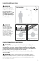
Installation Preparation Make sure the installation site you choose allows the fan blades to rotate without any obstruction. Allow a minimum clearance of 7 feet (2.1 meters) from the floor to the blades and 30 inches (76 cm) from the wall to the end of the blades. WARNING Your new ceiling fan will require a grounded electrical supply line of 120 volts AC, 60 Hz, 15 amp circuit. The outlet box must be securely anchored and capable of withstanding a load of 35 lbs (15.9 ww kg).
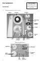
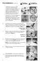
Fan Installation Tools Needed A stepladder, phillips head screwdriver and a wire stripper Instructions 1 Remove and identify contents of carton.
See Page 2 WARNING Circuit Breaker POWER OFF 2 Carefully insert blades into rotor slots, and using pan head screws from hardware package, secure blades to rotor. 3 Set fan body on either piece of packing foam, bottom side up. Remove four, phillips head rotor screws from motor and set aside for Step 4. Do NOT remove the white multi-point (star-drive) screws.. 4 Rotate motor so that the empty screw holes from Step 3 are aligned with the notches in the center hub.
Fan Installation (continued) See Page 2 WARNING Feed bridge connector through center hole of LED board and carefully insert two-pin connector into terminal on the LED board. Gently push excess wire behind light cup and place LED board flat on light plate with cutouts positioned over the three attachment holes. Align LED cover with fastening holes positioned over cutouts in LED board and attachment holes on light plate. Use short panhead screws to secure LED cover and LED board in place on light plate.
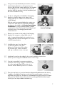
11 Using screws provided with junction box, securely attach hanging bracket to ceiling junction box. Junction box must be visibly marked as “Acceptable for Fan Support.” It is recommended that the flat washers and lock washers from the hardware pack be used for added security. 12 Lift fan to ceiling and set half ball in the hanging bracket so that the ridge on the edge of the hanging bracket is seated in the slotted channel in the half ball.
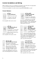
Control Installation and Wiring When ordering your fan, you should have selected the control that was most appropriate for your fan, electrical requirements and desired functionality. Controls are intended for use with one fan (except #FC-009A/009B as noted). Control Options #FC-001 Fan Speed Control A basic fan control used to operate one fan only, providing four speeds. Not compatible with remote control. #FC-002 Three Wire Fan Speed & Light Control For operation of one fan with light.
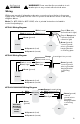
WARNING!! Power must be disconnected at circuit breaker prior to any contact with electrical wires. See Pages 2-3 WARNING Wiring With power turned off at breaker, make wire connections from the fan to the power supply at the ceiling and from the control to power at wall box as shown in the wiring diagrams below. Note: For #FC-009A or #FC-009B, refer to printed instructions included in control box/packaging.
Control Installation and Wiring (continued) Circuit Breaker POWER OFF Receiving Unit Wiring Detail (for #003, #004 and #005 only): With fan suspended from ceiling and with power off at breaker box, make wire connections as shown below. The receiving unit sits in the ball hanging bracket as shown in pictured (a) below.
See Pages 2-3 WARNING Dimming Selector Switch (for #003, #004 and #005 only): The remote handset (#003/#005) and wall control (#004/#005) ship pre-set for “on/off” operation of the light. The LIGHT button will turn the light on and off when pressed and released. To enable dimming function on the remote handset, move the vertically oriented dip switch down from ON to 1 (or from X to D). On the wall control, move the right (or lower) dip switch from ON to 2 (or from X to D).
Troubleshooting Please read all installation instructions carefully. After reviewing the following troubleshooting tips, if you are unable to solve a problem with the installation or operation of you fan, please contact customer service for additional assistance. I mportant : Do not return a fan or fan parts without first contacting us for troubleshooting assistance.
Fan makes repetitive ticking noise... • Check for obstructions in rotor path. • Make sure mounting hardware at ceiling is secure. • Make sure all other hardware and blade attachments are tight. • Give fan adequate “break in period” of several hours to several days then repeat steps above. Fan makes humming noise... • Be sure you are using a fan speed control with specific speed settings. Rheostats or continuous dimmers will cause motor noise. • Be sure that all fittings (light kit, bottom dome, canopy, etc.
Maintenance See Pages 2-3 WARNING Circuit Breaker POWER OFF Before servicing or cleaning your fan, switch power off at service panel and lock the service disconnecting means to prevent power from being switched on accidentally. When the service disconnecting means cannot be locked, securely fasten a prominent warning device, such a tag, to the service panel. • Your fan uses maintenance free, sealed bearings. There is no need to lubricate the motor bearings or inner shaft.
Lifetime Limited Warranty All products manufactured and sold by us. meet the highest industry standards. We use only the finest materials and production processes resulting in quality ceiling fans backed by the following warranty: Motors (dry locations):........................................................................................................Lifetime Motors (damp locations):................................................................................................. 10 years Light Kits:...