
Owner Manual


9
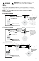
Wiring
With power turned off at breaker, make wire connections from the fan to the power
supply at the ceiling and from the control to power at wall box as shown in the wiring
diagrams below.
Note: For #FC-009A or #FC-009B, refer to printed instructions included in
control box/packaging.
#FC-001 Wiring Diagram
Green (ground)
Cap off Blue wire
(unused load for light)
Cap off Orange wire
if present (unused
neutral for light)
White (neutral)
Black (motor)Black (to motor)
Fan
Control
#FC-002 Wiring Diagram
Green (ground)
White (neutral motor)
Black (motor)
Blue (light)
Black (to motor)
Blue (to light)
Fan
Control
#FC-003/#004/#005 Wiring Diagram
Green
(ground)
White (neutral motor)
Black (motor)
White
Black
Blue (light)
Fan
Receiving
Unit
Green (ground)
connect ground
wire to grounded
hanging bracket
or mounting plate
Green (ground)
connect
ground wire to
grounded
hanging bracket
or mounting
plate
Green (ground)
connect ground
wire to grounded
hanging bracket
or mounting
plate
Orange
(neutral light if wire present)
#004/#005
Wall Switch
(or use #003
On/Off
Switch)
Orange (neutral light)
A/C power in (neutral)
A/C power in (load)
A/C power in (neutral)
A/C power in (load)
A/C power in (neutral)
A/C power in (load)
WARNING
See Pages 2-3
WARNING!! Power must be disconnected at circuit
breaker prior to any contact with electrical wires.