P 200 AIS Chartplotter USER MANUAL
FOREWORD We thank you for the purchase of your new P200 AIS Chartplotter. Wherever you sail now, you can have a better overview of your surroundings at sea and voyage with more safety. P200 is strictly tested to meet the rigorous demands of the marine environment. With proper installation and use, the equipment will serve loyally and reliably at its optimum. For sales, services, and technical supports, please contact your local AMEC representatives or Alltek Marine Electronics Corp. . at sales@alltekmarine.
COPYRIGHT The entire contents of this instruction manual, including any future updates, revisions, and modifications, shall remain the property of AMEC at all times. Unauthorized copies or reproduction of this manual, either in part or whole, in any form of print and electronic media, is prohibited. The contents herein can only be used for the intended purpose of this manual. DISCLAIMER AMEC is devoted to maintaining the correctness of this product manual.
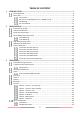
TABLE OF CONTENT 1 INTRODUCTION .................................................................................................................................. 7 DEVICE OVERVIEW ................................................................................................................ 7 ABOUT AIS ......................................................................................................................... 9 What is AIS? ....................................................................
Help ................................................................................................................................ 47 4 SPECIFICATIONS ...............................................................................................................................48 PRODUCT SPECIFICATIONS ....................................................................................................48 DIMENSIONS .........................................................................................
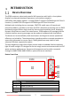
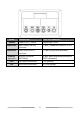
INTRODUCTION Device Overview The P200 contains a robust and powerful AIS transceiver with built-in chart plotter display for enhanced situational awareness and intuitive navigation. P200 offers two product options: 1) model P200-CS supports CSTDMA-type AIS Class B function; 2) model P200-SO supports SOTDMA-type AIS Class B function. Multiple tools including alarms, messages, CPA/TCPA notify users of hazards and potential problems, provided in real time by P200´s advanced processing unit.
NAME POWER NMEA2000 NMEA0183 Ethernet (OPTIONAL) GPS VHF DESCRIPTION Power in, 12V / 24V DC NMEA 2000 (CAN bus) connector NMEA 0183 (RS-422) connector Ethernet connector (OPTIONAL) GPS antenna connector VHF antenna connector TYPE OF CONNECTOR Round type, 3 pins 5 pins, standard connector LEN=1 12 pins (4 pins are reserved) 8 pins (with a cable connecting to RJ45 connector) TNC (female) SO-239 (female) 8
About AIS What is AIS? The Automatic Identification System (AIS) is a Very High Frequency (VHF) radio broadcasting system that transfers packets of data over the VHF data link (VDL) and enables AIS equipped vessels and shore-based stations to exchange identification information and navigational data. Ships with AIS transceivers continually transmit their ID, position, course, speed and other data to all nearby ships and shore stations.
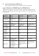
AIS on Search and Rescue (SAR) Aircraft: used on airplanes and helicopters to assist search and rescue operation. AIS Class A vs. SOTDMA Class B vs. CSTDMA Class B A brief comparison between class A and class B AIS is illustrated in the following table. P200-SO is an SOTDMA-type class B AIS transponder, P200-CS is a CSTDMA-type class B AIS transponder. Type of AIS Class A Class B-SO Class B-CS Transmit Power 12.
AIS Message P200 exchanges the following navigational data with other AIS equipped vessels within VHF range to increase the safety of your journey at sea: Static data: MMSI Vessel name Vessel call sign Type of ship Ship dimensions / GPS antenna location Dynamic data: Position of the vessel Course over ground (COG) Speed over ground (SOG) True heading P200 transceiver receives also safety related messages (SRM) from other vessels or persons who are in distress.
AIS Transmit Rate P200-CS (CSTDMA Class B AIS) broadcasts ship dynamic data per following reporting interval. Besides, ship static data will be broadcasted every 6 minutes. Ship Condition Nominal Reporting Interval Ship not moving faster than 2 knots 3 minutes Ship moving faster than 2 knots 30 seconds P200-SO (SOTDMA Class B AIS) also broadcasts ship´s static data every 6 minutes.
INSTALLATION Equipment in the Box 13
Connection Diagram Note: The Ethernet connector is not included in the standard model.
Installation Procedures Please familiarize the manual content before begin installation. Depending on your hardware configuration, use the following recommended steps for installation.
Device (Main Unit) Installation Table Mounting 1) 2) 3) 4) Place the mounting bracket to the location where the AIS unit is to be installed. Fix the bracket with five (5) tapping screws. Install the AIS unit into the bracket hook. Fix the AIS unit with the two fixing knobs as supplied in the package.
Flush Mounting 1) 2) 3) 4) 5) Make a rectangle hole at the location to be installed, using the panel mount cutting template. Remove the two (2) plastic screw covers which are fitted on the top and bottom sides of the display front face. Confirm whether the AIS unit and the rectangular hole meet or not. Correct the rectangular hole if it is defective. Put the AIS unit on the opening and fix with four (4) tapping screws. Refit the plastic covers removed in step (2).
VHF Antenna Installation The quality and positioning of the antenna are the most important factors dictating AIS performance. It is recommended that a VHF antenna with omnidirectional vertical polarization be specifically tuned for marine band. Since the range of VHF signals is largely decided by line of sight distance, the VHF antenna should be placed as high as possible and at least 5 meters away from any constructions made of conductive materials.
GPS Antenna Installation Install the GPS antenna where it has a clear view to the sky, so that it may access the horizon freely with 360° degrees. 5˚ Ensure a free 360˚ horizon with a vertical observation of 5˚. 3m The recommended horizontal distance between GPS antennas and other antennas is 3m. GPS Antenna Locations It is recommended to keep the GPS antenna out of the transmitting beam of highpower transmitters such as Inmarsat devices and radar.
Cable Connection Connection with VHF Antenna Note: The VHF antenna and cable is not included in the standard supply.
Connection with GPS Antenna Note: The GPS antenna and cable is not included in the standard supply.
Connection with NMEA 0183 23
Connection with NMEA 2000 Note: The NMEA 2000 T-connector and cable is not included in the standard supply.
OPERATION Chart Display and Controls P200 is designed to operate in an intuitive way. All the functions can be served either by touch screen or with buttons. Function Touchscreen Buzzer Menu Home Zoom-In Zoom-Out Arrow Key ESC Enter Fn Power MicroSD card reader Description The touchscreen can be used to control the AIS chart plotter The buzzer can provide an audible sound when a key is pressed, a message is received, or an alarm is activated.
Turning the AIS Transceiver on Once P200 is connected to a power supply, press the power button and the AIS transceiver will start immediately. User will be asked to read and agree the End User License Agreement (EULA).
Setup Wizard If P200 detects that the MMSI is not set yet, a Setup wizard will help you configure important settings on your P200. The SD Card Slots tab informs that SD 1 is designed for C-map charts, while SD 2 is dedicated for data logging and firmware upgrade. Once a micro SD card is inserted, the tab will also display that map card is detected and its capacity.
The following tabs “Ship Static Data” and “Ship Dimension” tab allow the users to configure the ship´s static data. Please note The input data will be written in P200 immediately MMSI can be set only once, please program your MMSI correctly. If the MMSI needs to be changed for any reason, please contact your dealer who will arrange to have the MMSI reset. Once the EULA is confirmed and the ship data set, the chart screen will be displayed which is the starting screen by default.
On-screen Information Function Speed Course Position HDG or Time Description Vessel speed over ground as taken from GNSS satellite data Vessel course over ground as taken from GNSS satellite data Vessel position taken from GNSS source Heading taken from heading sensor. When HDG is not available, UTC will be displayed on this place which is derived from GNSS satellites or AIS Base Stations. The information of the 4 fields above is only available when the AIS has a valid GPS position fix.
Menu Alarms Open the sub menu of the individual menu selected in the Home panel When there are active alarms, acknowledged or unacknowledged, the icon “ALARM” will appear. When pressing on the ALARM icon, the “Alarms” menu will be opened to display all the currently active alarms in a list. Press the Home button to open the home menu. Press the button to control the display dimming. When pressing repeatedly on the icon, the brightness will be reduced to minimum, then increased to maximum.
Chart The P200 contains an application which will display AIS targets received, along with its own vessel position on a basic world chart by default. It supports the C-MAP 4D to provide more detailed and high-resolution charts which can be purchased separately by C-MAP dealers. The basic chart operations: The chart can be scrolled up, down, left, and right using the touch screen or the arrow keys. The chart can be zoomed in or out with pinch gesture or with the zoom-in and zoom-out keys.
Man Overboard (MOB) activation When pressing the Fn Key and select “Man overboard”, you can create a Man Overboard (MOB) for an emergency. This means: A waypoint at the vessel´s current position is created The display switches to chart panel, centered on vessel´s position Navigational information (bearing, range and time to go based on vessel´s speed) will be displayed until MOB is cancelled Delete MOB: Press Fn key again and confirm the option “Cancel Man Overboard”.
When pressing the Fn key and select “Go to Own Vessel”, your vessel onscreen will be centered.
The ‘Options’ menu for the chart is available for more advanced features. Within the ‘Options’ menu, the chart can be oriented to either North, Heading, or Course Up. Vessel Look Ahead: in North-Up mode, the chart will be set so that the own vessel position is always in the centre of the screen. By head-up or course-up, an additional room ahead the vessel will be added for a better navigation. Show Distance Rings: shows or hides distance rings.
Plot View Plot view is the screen to show the location of other AIS targets relative to your own vessel. The own vessel´s static data is displayed on the blue bar. The plot range from 0.1NM up to 1000NM can be adjusted by pinching the touch screen or pressing the zoom-in or zoom-out buttons. In Plot view´s menu, the 3 different orientation modes can be selected.
Targets The ‘Target List’ screen is the primary screen for displaying AIS targets received. The targets are sorted by default by TCPA. Press the first row of each any column to sort with range, bearing, CPA or TCPA, either in ascending or descending order. Scroll up or down to navigate all the targets with either touch screen or arrow keys. The vessel details of the selected target will be displayed on the right side of the screen.
Alarms When there are any active alarms coming in, a New Alarm(s) window will pop up. The alarms can be either acknowledged one by one by pressing on the “Acknowledge” button or all at once by pressing the button “Acknowledge All and Show Details” to switch directly to the Alarms menu. All the active alarms are listed by time stamp in descending order. User can find further info about the alarms in the column on right hand side. Possible alarm conditions are listed in the Table below.
ALR AIS: TX Malfunction AIS: Antenna VSWR exceeds limit AIS: RX Channel x malfunction (AIS: Rx channel 1 malfunction, AIS: Rx channel 2 malfunction) AIS: General failure AIS: No position sensor in use AIS: No valid SOG information AIS: No valid COG information Description A Tx Malfunction alarm is generated if a malfunction in the radio transmitter hardware such as low Tx power or frequency drift is detected. The VSWR (Voltage Standing Wave Ratio) of the antenna is checked by every transmission.
Messages The Messages is an application to receive, send and compose messages. All the received messages are saved in Inbox, while the sent messages are stored in Outbox. The messages are displayed by time in descending order. The inbox and outbox can both save up to 100 messages. When there are more than 100 messages in inbox or outbox, the oldest messages will be overwritten.
In the Outbox, the user is giving the opportunity to compose new messages. Select the message type (broadcast or addressed) and destination and type the message with the on-screen keyboard.
Options 41
Options→General→User Settings Parameter Name Key/Touch Beep Time Settings Description From the scroll-down list, the key/touch beep volume can be selected between Off/Normal/Quiet/Loud Here the „Time Zone“, “Time Format” and “Date Format” can be user defined per the scroll-down list Options→General→Alarm Settings Parameter Name Alarm Sound CPA/TCPA Settings Description The alarm sound can be switched on or off here The AIS transceiver can be configured to identify approaching vessels which fall within ce
Ship Dimensions Select the ship type (and cargo type when available) according to ITU 1371-3 from the drop list. Enter the vessel dimensions by appointing the position of your GPS antenna Options→Interfaces Parameter Name NMEA 0183#1 NMEA 0183#2 Description The default NMEA 0183#1 baud rates are 38400-bps. Input and output baud rate can be assigned separately. The default NMEA 0183#2 baud rates are 4800-bps. Input and output share the same baud rate.
Device Information The Device Information can be accessed by pressing on the icon, or pressing the lower-left corner on chart or plot view where the latitude and longitude are displayed. The default screen of Device Information is GNSS Status.
GNSS Status The GNSS Status page shows the current GPS signal strength along with GPS position fix information. Satellite signals shown in green are actively being used to calculate a position. If a position fix is not available, then no position information will be displayed and the signal strength bars will be shown in blue. The “Fix” mode indicates how the position fix is done: 2D means a two-dimensional position fix that includes only horizontal coordinates.
SW/HW Information Parameter Name SD Card Slots SW/HW Info System Updates Description The “SD Card Slots” reminds that SD Card slot 1 is dedicated for C-MAP card compatible with C-MAP 4D format only. When an SD card in slot 2 is detected, it´s total and remaining capacity will be displayed here This view displays the software and hardware versions running on the device as well as its serial number which are useful information for error diagnostics.
Help Parameter Name Support About EULA License Description To display manufacturer´s service email address and other contacts for facilitating technical support Copy right statement of the manufacturer End User License Agreement To display other licenses used in this device 47
SPECIFICATIONS Product Specifications APPLICABLE STANDARDS IEC 60945 Ed. 4:2002 IEC 62287-1 Ed. 3:2017 (P200-CS) IEC 62287-2 Ed. 2:2017 (P200-SO) IEC 61108-1 Ed. 2:2003 ITU-R M.1371-5:2014 EN 300 328 V2.2.2 EN 62368-1:2014 + A11:2017 EN 303 413 V1.1.1 EN 301 489-1 V2.1.1 / EN 301 489-19 V2.1.1 EN 301 489-1 V2.1.1 / EN 301 489-17 V3.1.1 EN 301 843-1 V2.2.
Viewing Angles Backlight Color typ./ min. 85°/ 80° top/bottom, typ./ min. 85°/ 80° left/right White LED POWER SUPPLY Power Input / Current (max) P200-SO: 12-24 VDC / 2.3-1.1A max P200-CS: 12-24 VDC / 2.3-1.
Dimensions 50
Supported NMEA 0183 Sentences Sentence GGA GSA GSV GLL RMC VDO VDM Sentence DTM GBS GSA HDT RMC ROT Transmit Description Global Positioning System Fix Data GNSS DOP and Active Satellites GNSS Satellites In View Geographic Position – Latitude/Longitude Recommended Minimum Specific GNSS Data AIS VHF Data-Link Own-Vessel Report AIS VHF Data-link Message Receive Description Datum Reference GNSS Satellite Fault Detection GNSS DOP and Active Satellites Heading, True Recommended Minimum Specific GNSS Data Rate Of
NMEA 2000 PGN Information PGN 59392 59904 60928 126464 126996 129025 129026 129029 129038 129039 129040 129041 129539 129540 129792 129793 129794 129795 129796 129797 129798 129800 129801 129802 129803 129804 129805 129806 129807 129809 129810 PGN 59392 59904 60928 127250 Transmit Description ISO Acknowledgment ISO Request ISO Address Claim PGN List - Transmit PGN's group function Product Information Position Rapid Update COG SOG Rapid Update GNSS Position Data AIS Class A Position Report AIS Class B Posit
127258 129026 129029 129539 Magnetic Variation COG & SOG, Rapid Update GNSS Position Data GNSS DOPs TROUBLESHOOTING P200 receives AIS signals normally, but no one in the surrounding can see me, why? AIS Class B transmission range limitation: an AIS Chartplotter transmitting range of 5-7 miles in perfect conditions. The AIS receiver in the transceiver will typically see Class A vessels that are 20-30 miles away or even more in excellent conditions.
vessel show up on their displays with just MMSI number without the vessel name. This is usually due to the receiving device not knowing how to process the Message 24 static data from Class B transceivers. Please contact the chart plotter maker and ask for software upgrades (for these older chart plotters) to resolve this issue. If you still encounter difficulties to set up or operate P200 correctly, please email to service@alltekmarine.com for further instructions.
ABBREVIATIONS AIS AtoN COG CPA CSTDMA SOTDMA DSC ECS ETA FM GPS GMSK GNSS HDG IMO MMSI NM NMEA PER POS Rx SART SOG TCPA TDMA Tx UTC VDL VHF VSWR VTS Automatic Identification System Aids to Navigation Course Over Ground Distance to Closest Point of Approach Carrier-Sense Time Division Multiple Access Self-Organized Time Division Multiple Access Digital Selective Calling Electronic Chart System Estimated Time of Arrival Frequency Modulation Global Positioning System Gaussian Minimum Shift Keying Global Navig
FCC INTERFERENCE STATEMENT NOTE: This equipment has been tested and found to comply with the limits for a Class A digital device, pursuant to part 15 of the FCC Rules. These limits are designed to provide reasonable protection against harmful interference when the equipment is operated in a commercial environment.
RF Exposure Warning WARNING: This device generates and radiates RF electromagnetic energy and must be installed and operated according to the instructions contained in this manual. Failure to do so may result in product malfunction and/or exposure to potentially harmful levels of radio frequency radiation. WARNING: Never operate this device unless it is properly connected to a VHF antenna. The system has a Maximum Permissible Exposure (MPE) radius of 1.2m from the antenna.
AMEC WORLDWIDE WARRANTY Limited warranty Subject to the terms, conditions and limitations set forth in this Worldwide Limited Warranty (hereinafter the “Warranty”), KODEN warrants that its products, when properly installed and used, will be free from defects in material and workmanship for a period of twelve (12) months, from the date of first purchase (the ‘Warranty Period’) For the purposes of this warranty, ‘date of first purchase’ means the date that the product was purchased by the first retail custome
Alltek Marine Electronics Corporation 14F-2, No. 237, Sec. 1, Datong Rd., Xizhi Dist., New Taipei City, 22161, Taiwan Tel: +886 2 8691 8568 Fax: +886 2 8691 9569 Email: service@alltekmarine.com Website: www.alltekmarine.