
Installation Guide


C
ONSEJO ÚTIL NÚM. 2:
P
ara quienes
no son intimidados por herramientas de
motor o son instaladores profesionales.
Puedes usar también una sierra circular
con discos de puntas de carburo para
hacer cortes rectos. Si empleas una her-
ramienta de motor, asegúrate de usar
gafas de seguridad y máscara contra el
polvo, y trabajar en un área bien ventilada
fuera de la habitación donde se instalará.
Asegúrate de eliminar todos los desechos
de corte que queden en todos los
mecanismos de encaje antes de instalar.
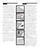
4. Al instalar allure
®
, se recomienda en-
fáticamente escalonar las filas de modo
que las uniones de los bordes cortos no
queden en una línea recta y uniforme. Re-
comendamos el método de escalonado
aleatorio para las tablas
(Figura 4)
. Mantén
un mínimo de 8" (30.5 cm) de escalonado
en la unión de extremo de una fila a otra
a lo largo de toda la instalación.
5. Comience la segunda fila con un corte
a la longitud deseada del tablón para una
apariencia escalonada deseada (tablón
de corte no debe ser inferior a 8 ").
Engancha el primer tablón de la fila 2,
conectando el lado largo con la primera
fila. Mantén un espacio de expansión de
¼ plg (64 mm) Entonces engancha el
segundo tablón conectando el lado largo
a la primera fila y deslizándolo hacia
arriba hasta el extremo corto del primer
tablón. Después ubica y encaja. Ver la
Figura 5.
Para asegurar un ajuste apretado,
use un bloque para martillar y un martillo
de cara suave en las largas costuras
(Figura 6)
, a continuación, toque abajo en la
parte superior de las tablas en las costuras
cortas
(Figura 7)
.
CONSEJO ÚTIL NÚM. 3: Si no tienes
un bloque para martillar, puedes usar un
recorte de tabla (aproximadamente 6 plgs
o 152 mm) como bloque para martillar.
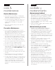
6. Al cortar una tabla para iniciar una fila,
siempre corta el lado corto de la tabla que
tiene el borde ranurado. Lo que sobre de
la tabla puede usarse en el lado opuesto
de la habitación, al final de esa fila, si la
distribución lo permite. Ver la Figure 8.
Para
un primer plano del mecanismo de bloqueo
de junta de extremo véase la
Figure 2
.
ENGLISH
8
ESPAÑOL
HELPF
U
L
HI
NT
#2:
Fo
r
t
h
o
s
e
wh
o
are
n
o
t
i
n
t
i
mi
d
at
e
d by
po
we
r
t
o
o
ls
,
o
r y
o
u’
re
a
p
ro
f
e
s
s
i
o
n
al i
n
s
t
a
lle
r
. Y
o
u c
an
als
o
us
e
a
c
i
rc
ular s
aw wi
t
h
c
arb
i
d
e
-t
i
p
pe
d blade
t
o
mak
e
s
t
rai
g
h
t
c
ut
s
. I
f
y
o
u us
e
a po
we
r
t
o
o
l,
be
s
ure
t
o
we
ar s
af
e
t
y
g
las
s
e
s
an
d
d
us
t
ma
s
k
a
n
d
wo
rk
i
n
a
we
l
l v
e
n
t
i
lat
e
d
are
a o
ut
s
i
d
e
t
h
e
ro
o
m o
f
i
n
s
t
alla
t
i
o
n
. B
e
s
ure
al
l
de
bri
s
f
ro
m
c
ut
t
i
n
g
i
s
re
mo
v
e
d f
ro
m
al
l
lo
c
k
i
n
g
me
c
h
an
i
s
ms
be
f
o
re
i
n
s
t
al
li
n
g
.
4
. Wh
e
n
i
n
s
t
alli
n
g
a
l
l
u
r
e
®
, s
t
a
g
g
e
r
t
h
e
ro
ws
s
o
t
h
at
t
h
e
s
h
o
r
t
e
d
g
e
s
e
ams
a
re
n
o
t
i
n
a s
t
rai
g
h
t
un
i
f
o
r
m l
i
n
e
.
W
e
re
c
o
mme
n
d
t
h
e
s
t
ag
g
e
re
d ran
d
o
m me
t
h
o
d
(
F
igu
re
4)
.
M
ai
n
t
ai
n
a mi
n
i
mum 8
-i
n
c
h
e
n
d-j
o
i
n
t
stagger fro
m
ro
w-to
-ro
w thro
ugho
ut the
entire instal
la
tio
n.
5.
Sta
r
t the sec
o
nd ro
w with a plank c
ut to
desired length fo
r desired
sta
ggered
app
earanc
e (c
ut plank sho
uld be no
l
ess
than 8"). Attac
h the first plank o
f Ro
w 2 by
c
o
nnec
ting
the lo
ng side to
the first ro
w.
Maintain yo
ur ¼ in expansio
n ga
p. T
hen
attac
h the
sec
o
nd p
la
nk
by c
o
nnec
ting the
l
o
ng side to
the first ro
w and sl
iding it up
to
the
sho
r
t
end o
f the first pl
ank. T
hen
dro
p
and
l
o
c
k.
See
F
igure 5
.
To
ensure
a
tight fit,
use a tap
p
ing blo
c
k
and
so
ft
fac
ed
hammer o
n
the
l
o
ng
seams
(F
igure 6)
,
then,
ta
p
do
wn
o
n
to
p
o
f
the pl
anks at
the
sho
r
t sea
ms
(F
igure 7)
.
HELPFU
L HI
NT #3:
If yo
u
d
o
n’t
ha
ve
a
ta
pp
ing blo
c
k,
yo
u c
an use a sma
ll
sc
rap
piece of the vinyl plank material (approxi
-
mately 6” or15
2
mm) as a tapping block
.
6. Wh
en c
uttin
g a pl
an
k to s
tart a row, you
w
il
l
n
eed to c
ut off th
e en
d w
ith
th
e groov
e.
The remaining piec
e c
an
th
en
be us
ed on
th
e oppos
ite s
ide of th
e room, at th
e en
d of
th
e row
if l
ayout permits
. See
Figu
r
e
8
. For a
c
l
os
e-up of th
e end joint l
oc
kin
g mec
h
an
is
m
s
ee
Figu
r
e
2
.
5
6
4
8
7