
Installation Sheet

LP316012
NOTICE
• The important safeguards and instructions outlined in this sheet cannot cover
all possible conditions and situations that may occur. It must be understood
that caution and certain care factors must be followed. These instructions are
provided for your safety and we highly recommend that a licensed, trained
electrician install this unit.
• This fixture is designed to be mounted on a correctly installed standard round
or octagon box OR through a wiring box with a plaster frame. The box must be
securely mounted to the structure of the building. The crossbar and hardware
supplied should be used, directly mounting the fixture to the outlet box may
make it impossible to correctly align the fixture.
Important: ALWAYS be sure to di
sconnect power before re-lamping or wiring the fixture. Read these instructions completely before starting installation.
To avoid the risk of fire and/or shock fixture must be installed in compliance to national and local electrical and building codes.
If an existing fixture is being replaced take special notice of which wires were connected in the outlet box.
DO NOT SEPARATE ANY WIRES THAT MAY BE EXISITING IN THE JUNCTION BOX
DO NOT DAMAGE THE INSULATION OF JUNCTION BOX WIRES.
In Regular circumstances the BLACK wire will be “live”, WHITE will be “neutral” and GREEN or BARE COPPER will be “ground”. In older buildings it is always good practice to
reconfirm the polarity of the wiring.
ASSEMBLY INSTRUCTIONS
CANADA : 102 ∙19028 27
TH
Ave. - Surrey, BC V3Z 5T1
USA : 3035 E. Lone Mountain Rd - Las Vegas, NV, 89081
www.aloralighting.com
P.
1.833.MY ALORA (692.5672)
WARNINGS AND CAUTIONS
TECHNICAL SUPPORT
1.833.MY ALORA(692.5672)
technicalsupport@aloralighting.com
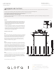
Step 1
Step 2
You are now ready to enjoy your fixture.
Attach the mounting plate (1d) to junction box (1a), using two junction box
screws (1j) (not provided). *For additional support install four anchor screws
(1h) and anchors (1f) through mounting plate into ceiling*. To assist in the
installation, support cables are included within the canopy. Secure the cables
(1h) to the mounting plate before wiring the fixture and connect the safety
cable link (1i) to the mounting plate. Cut down the extra wire and connect
fixture wires to junction box wires using the marrettes provided (1b). (white to
white “N”, black to black “L”, green to green “G”). Place the canopy over the
mounting plate and secure it by sliding the mounting collar (2b) up and
threading to secure the fixture to the ceiling.
Remove the mounting plate (1d) from within the canopy (2a) by loosening the
two canopy pivots (1g). Determine the desired length the fixture will hang by
selecting from the assorted rod sizes supplied (2c). Slide selected rods
through the fixture wires and thread the rod assembly to fixture body (3a).
Secure the fixture assembly to the canopy by feeding the fixture wires
through the mounting collar, fixture pivot and canopy and thread the rod
assembly to the fixture pivots (1g) (figure 1).
Step 3
Install recommended lamps (3c) (not provided) (referred on the socket label
for maximum wattage and type) to fixture sockets (3b). Secure the glass
shades (3d) by placing them over lamps and securing in the shade holders
(3b). Finally restore power. *If fixture has integrated LED (Lighting Emitting
Diodes) lamp installation is not required*
Linear Pendant
1a.
1c.
1d.
2a.
2b.
2c.
1b.
1e.
1f.
1g.
3d.
3c.
3b.
3a.
Figure 1
1h.1i.1j.