Installation and Servicing Instructions Alpha 240XP and 240XE Wall Mounted, Fan Assisted, Room Sealed, Gas Fired Combination Boilers For Technical help or for Service call ... ALPHA HELPLINE Tel: 0870 3001964 Nepicar House, London Road, Wrotham Heath, Sevenoaks, Kent TN15 7RS Service Listed 0051 Alpha 240XP Alpha 240XE G.C. No. 47 532 10 G.C. No.
CONTENTS 1 2 3 4 5 6 Introduction ....................................... 2 Technical data ................................... 3 General boiler information .................. 7 Installation ......................................... 11 Commissioning ................................. 16 Boiler operation ................................. 18 1 7 8 9 10 11 12 Routine servicing ............................... 19 Component replacement ................... 21 Wiring diagrams ................................
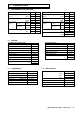
2 2.1 TECHNICAL DATA PERFORMANCE - NATURAL GAS Central Heating MAX. MIN. Domestic Hot Water MAX. MIN. Heat Input (Gross) kW Btu/h 28.63 97 700 11.76 40 150 Heat Input (Gross) kW Btu/h 28.63 97 700 11.76 40 150 Heat Output (modulating) kW Btu/h 23.3 79 500 9.3 31 700 Output to Water (modulating) kW Btu/h 23.3 79 500 9.3 31 700 Burner Pressure Room sealed chamber panel fitted mbar in wg 9.6 3.84 1.1 0.44 Burner Pressure Room sealed chamber panel fitted mbar in wg 9.6 3.84 1.
2.5 GENERAL 2.6 Dimensions ELECTRICAL Height 900 mm Supply Width Depth 450 mm 360 mm External Fuse Power Consumption 230/240 V ~ 50 Hz 3A 170 W Gas Connection Primary Water Content 22 mm 1.7 L Internal Fuse Electrode Spark Gap 240XP F2 A 5 mm Air Duct Diameter Flue Duct Diameter 100 mm 60 mm 240XE Thermocouple (240XP only):- 3.0 to 3.5 mm min. closed circuit output 2.7 10 mV FLUE LENGTHS Flue length = 0.
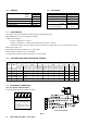
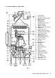
2.10 BOILER SCHEMATIC - Alpha 240XP 1 - Pressure gauge 2 - Gas service cock 3 - Mains inlet on/off valve and filter 4 - Diverter valve assy.
2.11 BOILER SCHEMATIC - Alpha 240XE 1 - Pressure gauge 2 - Gas service cock 3 - Mains inlet on/off valve and filter 4 - Diverter valve assy.
3 3.1 GENERAL BOILER INFORMATION GAS SUPPLY The boilers require a gas rate of 2.74 m³/h (96.76 ft³/h). The meter and supply pipes must be capable of delivering this quantity of gas in addition to the demand from any other appliances in the house. The boiler requires at least a 22 mm gas supply pipe. The complete installation, including the meter, must be tested for gas soundness and purged as described in BS 6891. 3.
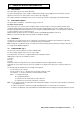
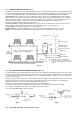
HORIZONTAL FLUE OPTIONS - Lmax = 4 metres L = B + C + 185 mm L = B + C + E + 185 mm B C B C E B F E C L = B + E + F + 185 mm + (90° bend = 1 metre) B L = B + C + 185 mm + (2 x 45° bends = 1 metre) VERTICAL FLUE OPTIONS Hmax = 4 metres Hmax = 3 metres Not less than 300 mm Not less than 450 mm Not less than 450 mm H H Fig.
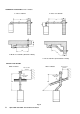
3.5 FLUE TERMINAL LOCATION - Fig. 5 Fig. 5 Terminal position Min. distance A Directly below an opening, air brick, windows, etc.
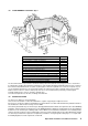
3.7 CENTRAL HEATING SYSTEM - Fig. 6 The boiler is designed for use in a sealed central heating system in accordance with the requirements of BS 5449 and BS 6798. The system should be designed to operate with flow temperatures of up to 82°C. When designing the system, the pump head, expansion vessel size, mean radiator temperature, etc must all be taken into account. Refer to the pump performance table for guidelines.
3.9 DOMESTIC HOT WATER SYSTEM The minimum flow rate needed for the flow switch and burner to operate is 2.5 litres/min. The incoming mains water pressure should be between 0.2 and 8 bar to ensure efficient operation. If the pressure is above 7 bar a pressure reducing valve must be fitted. To ensure economic use, the pipe runs between the boiler and taps should be in 15 mm copper pipe and be as short as possible. Where possible the pipework should be insulated to reduce heat loss.
4.3 Ensure line is level PREPARE THE WALL - Figs. 10, 10A 1. Decide upon the position of the boiler taking into account the clearances required for servicing and the flue terminal position. 2. Tape the template to the wall (ensure it is level and the right way up) and mark the position of the holes for the boiler mounting bracket and bottom fixings. If rear exit flue is used, mark the position of the hole for the flue.
A - Heating flow (22 mm) B - Hot water outlet (15 mm) C - Gas inlet (22 mm) D - Cold water mains inlet (15 mm) E - Heating return (22 mm) F - Pressure relief valve (15 mm) Note: Both Heating return and Cold water mains inlet valves contain serviceable filters. 20 23 95 65 A 65 B 65 C 65 D 55 E F Fig. 11 4.6 1. FIT THE FLUE - Figs. 12, 13 The following procedure applies to both rear or side exit flue. The only difference being the lengths to which the ducts are cut.
Inner flue duct length Outer air duct length 20 120 77 20 Outer duct clamp and seal Inner duct clamp 90° bend Terminal Flue sealing collar Ensure joint of inner clamp is at bottom Boiler 90 Note: For horizontal flue ensure there is a slight downward slope towards terminal. 190 Fig. 12 - Rear flue Outer duct clamp and seal 120 Inner duct clamp Seal 77 20 Bend clamp and seal Restrictor Screw 20 125 20 36 Boiler 225 225 Outer air duct length Inner flue duct length Fig. 13 - Side flue 4.
7. Fit the flue terminal to the outer duct by inserting it into the end with two holes. Align the holes and secure with the two screws provided. 8. Place the inner flue duct back into the outer duct. Use the inner duct supports to centralise the duct in the outer duct. 9. Fit the flue assembly as described in the previous section. Due to the size of the flue clamps the flue must be fitted from inside the building. 10.
5 5.1 COMMISSIONING FILL THE SYSTEM 1. The boiler is fitted with an automatic air vent positioned on the pump (see Fig. 2 or 3). The vent is fitted with a non-sealing cap. 2. Open the central heating flow and return valves (spindle flats in-line with valve) (see Fig. 11). 3. Open the fill point valve on the filling loop until water is heard to flow. To aid venting, the boiler drain point (see Fig. 35) may be opened until water flows out. Close the drain point as soon as water appears. 4.
5.3 TEST FOR GAS SOUNDNESS AND PURGE THE SUPPLY 1. With the boiler gas service cock closed (spindle flats at right angles to valve). Pressure test the gas supply and inlet pipework connection to the boiler gas service cock for soundness in accordance with BS 6891. 2. Loosen the gas inlet pressure test point screw on the gas valve (see Fig. 17). Ensure the gas supply is on and open the boiler service cock to purge in accordance with BS 6891. 3.
5.6 1. 2. 3. 4. FINAL COMMISSIONING Allow the heating system to heat up, then balance the system to achieve the necessary temperature difference across the heating flow and return pipes at the boiler and check the system volume and pressure. (Refer to Technical Data, sections 2.8 and 2.10). Turn off the boiler. Thoroughly flush out the water pipework and clean the filters in the heating return and mains water inlet isolating valves. Re-pressurise the system as described in section 5.1. 5.7 1. 2. 3. 4. 5.
6.2 DOMESTIC HOT WATER MODE When a demand for hot water (by opening a hot tap, etc.) is sensed by the flow switch, the pump starts and the burner lights at its middle output, increasing to its maximum output. Water in the boiler is then diverted from the central heating system to the domestic hot water heat exchanger, heating the incoming mains water. The burner output is varied to maintain the temperature of the hot water as that set by the adjustable temperature selector.
7.2 1. PREPARE FOR SERVICING - Fig. 18 Ensure the electrical supply is isolated and the gas supply is off. 2. Remove the two screws securing the top of the front casing. Lift the cover up slightly and remove. 3. Remove the four screws securing the room sealed chamber panel and remove the panel, taking care not to damage the seal. 4. Remove the two fixing screws (one each side) securing the control panel.
7.4 RE-ASSEMBLE THE BOILER 1. Replace the burner, ensuring it is located correctly over the injectors and the four locating pins (two each side). 2. Replace the combustion chamber front cover, ensuring the bottom is correctly located in the burner. 3. Alpha 240XE - Ensure the electrode leads are connected and the seals are in position in the bottom of the inner case. Alpha 240XP - Refit the pilot assembly and pilot shield to the burner.
8.3 PILOT COMPONENTS (Alpha 240XP only) - Fig. 19 Gain access as in section 8.1. Disconnect the thermocouple and pilot supply from the gas valve. Remove the pilot assembly from the burner. 1. Thermocouple Disconnect from the pilot burner and withdraw through the grommet. Carefully bend new thermocouple to match the old one, pass it through the seal and connect to the pilot burner. 2. Electrode Disconnect the lead from the electrode, unscrew the nut and withdraw the electrode.
8.6 ELECTRODES (Alpha 240XE only) - Fig. 20 Gain access as in section 8.1. 1. Remove the five screws securing the combustion chamber front cover and remove the cover. 2. Disconnect the leads from the electrodes. 3. Withdraw the main burner out of the boiler. Take care not to damage the side insulation panels. 4. Flame sensing electrode Remove the screw securing the electrode and withdraw the electrode. Fit the new electrode, ensuring it is positioned correctly (see Fig. 20). 5.
8.9 FAN - Fig. 21 1. Gain access as in section 8.1. 2. Remove the five screws securing the combustion chamber front cover and remove the cover. 3. Disconnect the air pressure tubes from the fan outlet. 4. Loosen the fan to flue adaptor clamp screws and raise the clamp as far as possible. 5. Remove the two screws securing the flue hood to the back panel and withdraw the assembly sufficiently to disconnect the fan wiring. 6. Remove the four screws securing the fan to the flue hood.
8.12 GAS VALVE (Alpha 240XP only) - Fig. 24 1. Gain access as in section 8.1. 2. Disconnect the thermocouple, pilot supply and overheat thermostat leads from the gas valve. 3. Disconnect the wiring and pressure tube from the gas valve. 4. Remove the screw securing the light grey cover around the gas control knob. 5. Remove the screw securing the microswitch assembly to the valve (access from beneath the boiler). 6. Remove the four manifold screws from beneath the boiler. 7.
8.15 IGNITION MICROSWITCH ASSEMBLY (Alpha 240XP only) - Fig. 26 1. Gain access as in section 8.1. 2. Remove the screw securing the light grey cover around the gas control knob. 3. Remove the screw securing the microswitch assembly to the valve (access from beneath the boiler). 4. Remove the 2-pin connector from the ignition PCB and remove the microswitch complete with cable. 5. Re-assemble in reverse order. 8.16 VIEWING WINDOW 1. Gain access as in section 8.1. 2.
8.21 IGNITION PCB (Alpha 240XP only) - Refer to Fig. 28 1. Gain access as described in section 8.1. 2. Remove the two fixing screws and disconnect the wiring. 3. Refer to Fig. 28, connect the wiring to the new PCB and re-assemble in reverse order. Relay PCB Ignition electrode leads Reset switch Ignition PCB Fig. 27 - Alpha 240XE Relay PCB Ignition lead Ignition PCB Fig.
8.22 MAIN PCB - Fig. 29 1. Gain access as described in section 8.1. 2. Disconnect all the wiring connectors from the PCB. 3. Remove the four fixing screws and carefully withdraw the board from the switch spindles. 4. Re-assemble in reverse order. Refer to the Wiring Diagram on page 34 or 35 for connections. Fixing screws Main PCB Fixing screws Fig. 29 Suppressor Blue 8.23 SUPPRESSOR - Fig. 30 1. Gain access as described in section 8.1. 2. Withdraw the suppressor from the control panel cover.
8.26 HEAT EXCHANGER 1. Drain the boiler heating circuit as described in section 8.2. 2. Remove the fan and flue hood assembly as described in section 8.9. 3. Carefully prise off the two clips from the heat exchanger to flow/return pipes. 4. Lift up the heat exchanger off the pipes. 5. Fit a new heat exchanger, ensuring the 'O' rings are in position in the flanges. Lubricating the 'O' rings with a soap solution with aid assembly.
8.29 TEMPERATURE SENSORS - Fig. 33 Note that both sensors are the same. 1. Gain access as described in section 8.1. 2. CH Sensor - Disconnect the wiring and unscrew the sensor. Re-assemble in reverse order with a new sensor. 2a. DHW Sensor - Close the mains cold water inlet valve and open the lowest hot water tap to drain the DHW system. Disconnect the wiring and unscrew the sensor. Re-assemble in reverse order with a new sensor, replacing the sealing washer if necessary. 8.30 AUTOMATIC AIR VENT - Fig.
8.33 PRESSURE RELIEF VALVE OR DHW INLET MANIFOLD - Fig. 35 1. Remove the DHW heat exchanger as described in section 8.32. 2. Disconnect the pump unions and withdraw the pump. 3. Disconnect the pressure relief valve outlet fitting, central heating return and mains water inlet valves. 4. Disconnect the two small flow sensing pipes from the manifold, and the small by-pass pipe from the rear of the diverter valve. 5.
Restrictor Differential pressure sensor Filter Fig. 36 8.36 MAINS WATER INLET VALVE FILTER - Fig. 37 1. Drain the boiler hot water circuit as described in section 8.2. 2. Unscrew the valve end cap fitting and withdraw the filter. 3. Clean or replace and re-assemble in reverse order. 8.37 HEATING RETURN FILTER - Fig. 37 1. Drain the boiler heating circuit as described in section 8.2. 2. Unscrew the heating return valve end cap fitting and withdraw the filter. 3.
8.39 DHW FLOW VALVE - Fig. 39 1. Drain the boiler hot water circuit as described in section 8.2. 2. Remove the flow switch assembly from the front of the diverter valve. 3. Disconnect the two flow sensing pipes from the flow valve. 4. Unscrew (not necessary to remove) the two screws securing the DHW flow valve to the diverter valve (one screw accessible from beneath the boiler) and withdraw the valve. 5.
9 WIRING DIAGRAMS 9.
9.
9.
9.
10 FAULT FINDING 10.1 CARRY OUT INITIAL FAULT FINDING CHECKS 1. Check that gas, water and electrical supplies are available at the boiler. i.e. Inlet gas pressure = 20 mbar Electrical supply = 230/240 V ~ 50 Hz CH water system pressurised to between 0.75 and 1.25 bar DHW flow rate is more than 2.5 litre/min 2. Carry out electrical system checks, i.e. Earth Continuity, Resistance to Earth, Short Circuit and Polarity with a suitable meter.
10.3 DOMESTIC HOT WATER - Follow operational sequence Turn selector to and go to section ' A ', page 41 Replace diaphragm YES YES Is mains water filter and differential assy. clean Turn thermostat to max. Open DHW tap fully. DHW flow valve operated NO YES DHW flow valve diaphragm damaged NO YES DHW flow rate more than 2.5 L/min.
10.4 CENTRAL HEATING - Follow operational sequence Turn selector to and go to section ' A ', page 41 YES 240 V across main terminal block, terminals 1 and N Turn Relay energised and contacts closed NO i.e. continuity between Replace relay PCB terminals 31, 32 on PCB YES External controls calling for heat thermostat to max.
10.5 FAULT FINDING SOLUTION SECTIONS A to L A 240 V at:1. Main terminals L and N NO 2. Main terminal fuse 3. 4. B C NO Check electrical supply Replace fuse NO Replace suppressor Both sides of suppressor NO PCB terminals 27, 28 Check wiring 240 V at:1. Pump YES If pump jammed, release NO NO Replace main PCB 2. PCB terminals 20, 21 1. CH system pressure 1.0 bar 2. Pump circulating water NO 3.
G Check and correct:1. Main PCB - Is plug connected to MET, i.e. Natural Gas 2. Main PCB - Is the RLA plug connected to OFF 3. 240XP only - Is wire connected on PCB between terminal 8 and F3 Modulating coil faulty i.e. correct cold resistance approx. 40 ohm YES Burner output modulates H Check and correct:1. Ignition electrodes and leads YES 2. Electrode connections 3. Spark gap and position YES Volts at Main PCB NO across terminals 41, 42 Max. burner press. approx. 10 V DC Min. burner press. approx.
11 SHORT PARTS LIST Reference Fig. 3, item 23 Fig. 2, item 23 Description Burner assembly Burner assembly Fig. 2 or 3, item 22 Fig. 2 or 3, item 26 Main injector 1.18 mm Primary heat exchanger and seals Fig. 2 or 3, item 9 Fig. 3, item 21 DHW heat exchanger and seals Gas valve - Honeywell VR4605AA1045 Fig. 2, item 21 Fig. 24 or 25 Gas valve - Honeywell V4600A1098 Gas valve modulating coil Fig. 2 or 3, item 15 Fig.
12 SERVICE HISTORY DETAILS OF BOILER INSTALLATION Date of Installation: ...................................................................... Name of Installer: ......................................................................... Address: ...................................................................................... .................................................................................................... ...............................................................................