
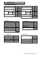
Technical data


10
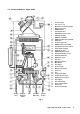
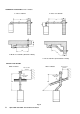
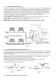
3.7 CENTRAL HEATING SYSTEM - Fig. 6
The boiler is designed for use in a sealed central heating system in accordance with the requirements of BS 5449 and BS 6798.
The system should be designed to operate with flow temperatures of up to 82°C. When designing the system, the pump head, expansion
vessel size, mean radiator temperature, etc must all be taken into account. Refer to the pump performance table for guidelines.
System volume - The expansion vessel incorporated into the boiler is suitable for a sealed heating system with a maximum
water content of 80 litres (18 gal). Above that, consideration should be given to fitting an additional expansion vessel fitted in
the position shown in Fig. 6. To check correct operation of the expansion vessel(s) the system pressure should not be more
than 2.5 bar when the system is at maximum operating temperature (for further guidance refer to BS 7074:1).
The boiler is supplied with the following components built in:-
Pressure relief valve - complying with BS 6759 and set to operate at 3 bar. The discharge pipe must be routed clear of the
boiler to a drain, in such a manner that it can be seen, but cannot cause injury to persons or property.
Pressure gauge - To indicate the system pressure to be maintained.
Expansion vessel - Conforming to BS 4814 with a capacity of 8 litres and pre-charged to a pressure of 0.8 bar.
By-pass - Where all radiators are fitted with thermostatic radiator valves an external by-pass may be required.
Alpha 240XP and 240XE - General Boiler Information
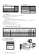
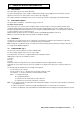
3.8 FILLING THE CENTRAL HEATING SYSTEM - Figs. 7, 8
The system design pressure (cold) should be set to 1.0 bar. This pressure is equivalent to a static head (see Fig. 6) of 10.2 metres of water.
Provision should be made to replace water lost from the system. This can be by manual or automatic means, as shown in Figs.
7 and 8. The position for connecting an automatic make-up vessel is indicated in Fig. 6. A double check valve assembly must
be used, as shown in Fig. 8.
Filling of the system must be carried out in a manner approved by the local Water Undertaking. Where allowed, the system may
be filled via a temporary connection as shown in Fig. 7. After filling, always disconnect the flexible hose of the filling loop.
All fittings used in the system must be able to withstand pressures up to 3 bar.
Drain taps (to BS 2879) must be used to allow the system to be completely drained.
The heating system should be thoroughly flushed before the boiler is connected and again after the first heating.
If it is required to add inhibitor to the system, refer to Alpha Therm Ltd. for guidance.
Refer to BS 5449 and BS 6798 for further information.
Feed cistern to be
located above highest
point in the system
Mains
water
supply
Stop
valve
Test cock
Double check
valve assembly
Overflow
Heating circuit
return
Heating circuit
return
Mains
water
supply
Double check
valve assembly
Stop
valve
Test cock
Air inlet
valve
Filling loop
temporarily connected
Hose
unions
Fig. 7 Fig. 8
Fig. 6
Note: A drain tap should be installed at the lowest
point of the heating circuit and beneath the appliance.
System
drain tap
Note: If the mains is fitted with water
meter, check valves or loose jumper stop
cock, then a DHW expansion device must
be fitted.
Static head of system
Make up vessel
DHW outlet
Mains water inlet
Additional expansion
vessel (if required)
Automatic
air vent
Boiler
casing
Heating flow
Heating return
Filling point
Double check valve assy.
By-pass could be a 15 mm pipe controlled
by a valve or an uncontrolled radiator.
Heating
by-pass
(If required)