Installation and Servicing Instructions Alpha SY9-24 Wall Mounted, Fan Assisted, Room Sealed, Gas Fired System Boiler For Technical help or for Service call ... ALPHA HELPLINE Tel: 0870 3001 964 Nepicar House, London Road, Wrotham Heath, Sevenoaks, Kent TN15 7RS Service Listed Alpha SY9-24 G.C. No.
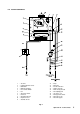
CONTENTS 1 2 3 4 5 6 Introduction ....................................... 2 Technical data ................................... 3 General boiler information .................. 6 Installation ......................................... 10 Commissioning ................................. 15 Boiler operation ................................. 17 1 7 8 9 10 11 12 Routine servicing ............................... 18 Component replacement ................... 19 Wiring diagrams ................................
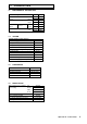
2 2.1 TECHNICAL DATA PERFORMANCE - NATURAL GAS Central Heating MAX. MIN. Heat Input (Gross) kW Btu/h 28.4 96 900 12.1 41 300 Heat Output (modulating) kW Btu/h 23.3 79 500 9.3 31 700 Burner Pressure mbar in wg 10.7 4.28 2.2 0.9 m³/h ft³/h 2.71 95.70 1.16 40.96 Settings Room sealed chamber panel fitted Gas Rate 2.2 SYSTEM Central Heating (Sealed System) Max. Working System Pressure 2.5 bar Min. System Pressure Max. System temperature 0.
2.5 GENERAL 2.6 ELECTRICAL Case Dimensions Height 720 mm Supply (without bottom tray) Width Depth 450 mm 330 mm External Fuse Power Consumption 3A 170 W Gas Connection Primary Water Content 22 mm 1.6 L Internal Fuse Electrode Spark Gap F2 A 2 to 4 mm Air Duct Diameter Flue Duct Diameter 100 mm 60 mm 2.7 230/240 V ~ 50 Hz FLUE LENGTHS Flue length = 0.75 m (not including the terminal, which is supplied with the boiler) Note: Additional flues (of the same length) are available.
2.
3 3.1 GENERAL BOILER INFORMATION GAS SUPPLY The Alpha SY24 boiler requires a gas rate of 2.71 m³/h (95.7 ft³/h). The meter and supply pipes must be capable of delivering this quantity of gas in addition to the demand from any other appliances in the house. The boiler requires at least a 22 mm gas supply pipe. The complete installation, including the meter, must be tested for gas soundness and purged as described in BS 6891. 3.
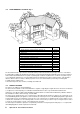
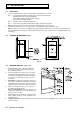
HORIZONTAL FLUE OPTIONS - Lmax = 4 metres L = B + C + 185 mm L = B + C + E + 185 mm B C B C E B F E C L = B + E + F + 185 mm + (90° bend = 1 metre) B L = B + C + 185 mm + (2 x 45° bends = 1 metre) VERTICAL FLUE OPTIONS Fig.
3.5 FLUE TERMINAL LOCATION - Fig. 4 Fig. 4 Terminal position Min. distance A Directly below an opening, air brick, windows, etc.
3.7 CENTRAL HEATING SYSTEM - Fig. 5 The boiler is designed for use in a sealed central heating system in accordance with the requirements of BS 5449 and BS 6798. The system should be designed to operate with flow temperatures of up to 82°C. When designing the system, the pump head, expansion vessel size, mean radiator temperature, etc must all be taken into account. Refer to the pump performance table for guidelines.
4 4.1 1. INSTALLATION UNPACKING The boxes required when the boiler is installed with a horizontal flue are as follows:Box 1 Cased boiler fitted with water and gas valves, union bends and washers Mounting bracket plus screws and wall plugs Flue terminal and flue sealing collar plus 2 screws Literature pack and Wall template Box 2 90° flue bend (not required for vertical flue) Box 3 0.
4.4 FIT THE BOILER - Refer to Fig. 10 1. Lift the boiler and locate it on the mounting bracket. 2. Fit the bottom screws to secure the boiler in position. Fig. 10 4.5 CONNECT THE PIPEWORK - Fig. 11 1. Thoroughly flush out all the water pipework. 2. The valves/fittings have been factory fitted, however, check that all the connections underneath the boiler have been tightened, especially the union bends.
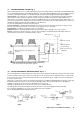
4.6 1. FIT THE FLUE - Figs. 12, 13 The following procedure applies to both rear or side exit flue. The only difference being the lengths to which the ducts are cut. Rear flue Outer air duct length = finished wall thickness + 135 mm. Inner flue duct length = finished wall thickness + 172 mm. Side flue Outer air duct length = finished wall thickness + the distance from the inside wall to the side of the boiler + 145 mm.
Fig. 13 - Side flue 4.7 FIT A FLUE EXTENSION - Figs. 12, 13 Note: 1. The maximum flue assembly length must not exceed a length of 4 metres. 2. If the flue is more than 1.5 m, the restrictor must be removed from the flue adaptor (see Fig. 13). 1. Withdraw the inner flue duct from the outer air duct supplied with the boiler. 2. Withdraw the inner flue duct from the extension.
4.8 CONNECT THE MAINS SUPPLY - Fig. 14 1. Gain access to the boiler terminal block by releasing the two fixing screws (one each side) securing the control panel and lowering the panel. Refer to Technical Data, section 2.9 for connection details. 2. Note: This boiler has been fitted with a mains supply cable.
5 COMMISSIONING When commissioning the boiler, ensure the Benchmark Log Book is completed. 5.1 FILL THE SYSTEM 1. The boiler is fitted with an automatic air vent positioned on the pump (see Fig. 2). The vent is always open and has no sealing cap. 2. Open the central heating flow and return valves (slot in-line with valve) (see Fig. 11). 3. Open the fill point valve on the filling loop until water is heard to flow. To aid venting, the boiler drain point (see Fig.
5.5 CHECK THE BURNER PRESSURES - Fig. 16 Set the central heating selector to 0 to turn the boiler off. Loosen the burner pressure test point screw on the gas valve and connect a pressure gauge. Allow the boiler to run for 10 minutes and check the burner pressures. 1. Set the selector switch to ON. 2. The burner will light at the ignition rate and will increase to the factory pre-set maximum output. Note: The burner pressure settings have been factory set and do not require adjusting.
6 BOILER OPERATION The boiler operation is controlled by the selector switch on the facia panel. When set to ON, it will provide central heating. 6.1 CENTRAL HEATING If there is a call for heat, the pump will start to circulate the central heating water. The fan will run at full speed; once the air pressure switch is proved the burner will light.
7 ROUTINE SERVICING To ensure efficient operation of the boiler it is recommended that it is checked and serviced as necessary at regular intervals. The frequency of servicing will depend upon the particular installation conditions and usage, but in general once per year should be adequate. It is the law that any service work must be carried out by a competent person, ie CORGI registered personnel. Warning: Before servicing the boiler, isolate the electrical supply and close the boiler gas service cock.
7.3 CLEANING THE BOILER 1. Remove any deposits from heat exchanger using a suitable soft brush. Do not use a brush with metallic bristles. 2. Check the condition of the combustion chamber insulation panels. Any damaged panels must be replaced. (Refer to Component Replacement, section 8.23). 3. Check the condition of the burner injectors on the manifold, carefully clean them with a soft brush if necessary. Do not use a brush with metallic bristles as this might damage the injectors. 4.
8.2 DRAINING THE BOILER - Refer to Figs. 2 or 11 Isolate the electricity supply and close the boiler gas service cock (see Fig. 11). Allow the boiler to cool. 1. Heating circuit Close the central heating flow and return valves (see Fig. 11). Connect a suitable pipe to the drain point (see Fig. 2) and route it to a suitable container. Open the drain point. Note: Some water will remain in the components and care must be taken when removing them. 8.3 IGNITION ELECTRODE LEAD - Refer to Fig. 21 1.
2 to 4 mm Flame sensing electrode Ignition electrodes 5 to 6 mm 5 to 6 mm Fig. 18 8.9 OVERHEAT THERMOSTAT - Fig. 19 1. Gain access to the combustion chamber as in section 8.1. 2. Disconnect the wiring from the overheat thermostat. 3. Remove the two fixing screws and remove the overheat thermostat from the heat exchanger. 4. Fit the new overheat thermostat and re-assemble in reverse order. Fig. 19 8.10 GAS VALVE - Fig. 20 1. Gain access behind the casing as in section 8.1. 2.
8.11 VIEWING WINDOW 1. Gain access behind the casing as in section 8.1. 2. Remove the rubber window frame and remove the damaged glass. 3. Re-assemble in reverse order with a new glass. Ensure the rubber frame is located correctly in the front panel. 8.12 INTERNAL FUSE - Refer to Fig. 14 The fuse is located in the boiler terminal block. 1. Gain access as described in Installation, section 4.8. 2. Lift out the fuse holder and remove the fuse.
8.16 PRESSURE GAUGE - Fig. 22 1. Gain access behind the casing and drain the boiler heating circuit as described in sections 8.1 and 8.2. 2. Remove the nut securing the pressure gauge sensor and withdraw the sensor. 3. Depress the two lugs on the pressure gauge and push it out of the control panel. 4. Fit the new gauge using a new washer on the manifold connection if necessary. 5. Refill and pressurise the system. (Refer to Commissioning, section 5.1). Fig. 22 8.
Fig. 23 8.21 PRESSURE RELIEF VALVE - Fig. 23 1. Gain access behind the casing and drain the boiler heating circuit as described in sections 8.1 and 8.2. 2. Remove the four screws securing the bottom tray and remove the tray. Disconnect the pressure relief valve outlet fitting. 3. Release the screw retaining the pressure relief valve and pull out the valve. 4. Re-assemble in reverse order. 5. Refill and pressurise the system. (Refer to Commissioning, section 5.1). 8.
9 9.
9.
10 FAULT FINDING 10.1 CARRY OUT INITIAL FAULT FINDING CHECKS 1. Check that gas, water and electrical supplies are available at the boiler. i.e. Inlet gas pressure = 20 mbar Electrical supply = 230/240 V ~ 50 Hz CH water system pressurised to between 0.75 and 1.25 bar 2. Carry out electrical system checks, i.e. Earth Continuity, Resistance to Earth, Short Circuit and Polarity with a suitable meter. Note: These checks must be repeated after any servicing or fault finding. 3.
10.
10.
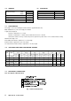
11 SHORT PARTS LIST Reference Description Fig. 2, item 3 Burner assembly Main injector 1.30 mm Fig. 2, item 4 Heat exchanger Gas valve - Honeywell VK4105M5009 Fig. 2, item 1 Fig. 24 Fig. 20 Fig. 20 Fig. 19 Fig. 22 Fig. 20 Fig. 14 Fig. 20 Fig. 2, item 10 Fig. 24 Fig. 24 Fig. 23 Fig. 2, item 15 Fig. 2, item 15 Fig. 2, item 16 Fig.
12 SERVICE HISTORY DETAILS OF BOILER INSTALLATION Date of Installation: ...................................................................... Name of Installer: ......................................................................... Address: ...................................................................................... .................................................................................................... ...............................................................................
Alpha Therm Limited. Nepicar House, London Road, Wrotham Heath, Sevenoaks, Kent TN15 7RS Tel: 0870 3001964 These instructions have been carefully prepared but we reserve the right to alter the specification at any time in the interest of product improvement. © Alpha Therm Limited 2003. email: info@alphatherm.co.uk website: www.alpha-boilers.com Part No. 1.